USB
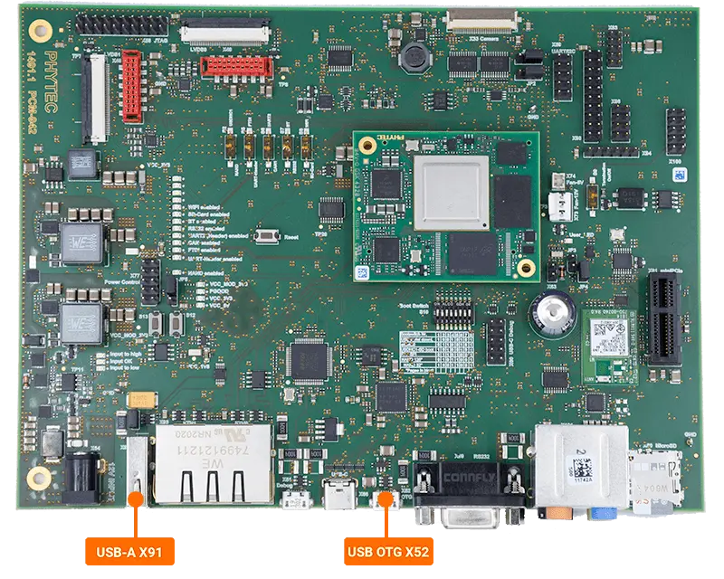
This guide will show you how to use the USB Host and USB OTG capabilities featured on the phyCORE-i.MX8X development kit.
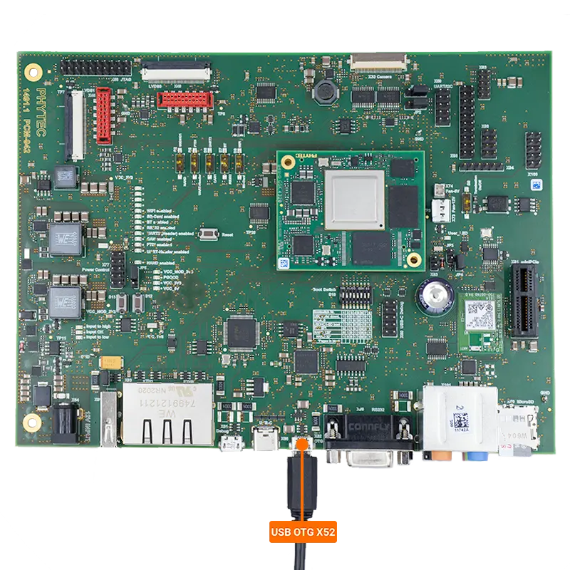
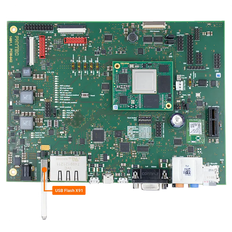
The USB Host interface uses a standard Type-A USB port (X91) and USB OTG interface uses a USB Micro-AB connector (X52).
Note
There is a USB-C interface (X66) but the USB-C device mode is currently not functional.

Requirements
USB Storage Device
USB Micro-AB to USB-A cable
Configuring the Development Kit for USB Host Mode
Make sure the development kit is set to USB Host mode.
Target (Linux)echo host > /sys/kernel/debug/ci_hdrc.0/role
Expected Output[ 310.955318] ci_hdrc ci_hdrc.0: EHCI Host Controller [ 310.960257] ci_hdrc ci_hdrc.0: new USB bus registered, assigned bus number 3 [ 310.979804] ci_hdrc ci_hdrc.0: USB 2.0 started, EHCI 1.00 [ 310.986406] hub 3-0:1.0: USB hub found [ 310.990380] hub 3-0:1.0: 1 port detected
Make sure gpio30 is set to USB_A by echoing “0” to value.
Target (Linux)cd /sys/class/gpio/ echo 30 > export echo out > gpio30/direction echo 0 > gpio30/value
USB Host Connection (FAT32)
[  483.133241] usb 3-1: new high-speed USB device number 2 using ci_hdrc
[  483.290193] usb-storage 3-1:1.0: USB Mass Storage device detected
[  483.296774] scsi host0: usb-storage 3-1:1.0
[  485.299788] scsi 0:0:0:0: Direct-Access     Kingston DataTraveler 3.0 PMAP PQ: 0 ANSI: 6
[  485.310579] sd 0:0:0:0: [sda] 30277632 512-byte logical blocks: (15.5 GB/14.4 GiB)
[  485.319027] sd 0:0:0:0: [sda] Write Protect is off
[  485.324390] sd 0:0:0:0: [sda] No Caching mode page found
[  485.329739] sd 0:0:0:0: [sda] Assuming drive cache: write through
[  485.374504]  sda: sda1
[  485.380370] sd 0:0:0:0: [sda] Attached SCSI removable disk
Verify the drive mounted successfully by viewing the contents of the drive:
Target (Linux)ls /run/media/sda1/
Write to the USB Host Device
Generate a random 10 MB file to test transferring data from the storage device.
Target (Linux)dd if=/dev/urandom of=test.file count=10 bs=1M
Expected Output10+0 records in 10+0 records out 10485760 bytes (10 MB, 10 MiB) copied, 0.271254 s, 38.7 MB/s
Copy the file to your storage device.
Target (Linux)dd if=test.file of=/run/media/sda1/test.file bs=1M
Expected Output10+0 records in 10+0 records out 10485760 bytes (10 MB, 10 MiB) copied, 0.0946181 s, 111 MB/s
Read from the USB Host Device
Copy the test file created during the write process back to the host.
Target (Linux)dd if=/run/media/sda1/test.file of=test1.file bs=1M
Expected Output10+0 records in 10+0 records out 10485760 bytes (10 MB, 10 MiB) copied, 0.0776833 s, 135 MB/s
Make sure the file was not corrupted during the transfer using md5sum.
Target (Linux)md5sum test.file md5sum test1.file
Expected Output2290972242afe72ec4c603bcbf51ca05 test.file 2290972242afe72ec4c603bcbf51ca05 test1.file
Unmounting the Drive
Warning
Make sure the drive is unmounted prior to physically disconnecting the device.
Failure to do so may result in loss of data and corruption of files
umount /run/media/sda1
Configuring the Development Kit for USB OTG Mode
Make sure your development kit is configured for USB OTG mode.
Target (Linux)echo gadget > /sys/kernel/debug/ci_hdrc.0/role
Expected Output[ 4225.033238] ci_hdrc ci_hdrc.0: remove, state 4 [ 4225.037768] usb usb3: USB disconnect, device number 1 [ 4225.047824] ci_hdrc ci_hdrc.0: USB bus 3 deregistered
Make sure gpio30 is set to USB_OTG by echoing “1” to value.
Target (Linux)cd /sys/class/gpio/ echo 30 > export echo out > gpio30/direction echo 1 > gpio30/value
Connecting the Development Kit to the Host PC
Connect the micro-USB cable between the USB OTG port (X52) and your Host PC.

Load the g_serial module.
Target (Linux)modprobe g_serial
Expected Output[ 4362.747928] g_serial gadget: high-speed config #2: CDC ACM config
Verify that the serial device “/dev/ttyGS0” exists.
Target (Linux)ls /dev/tty*
Expected Output/dev/tty /dev/tty21 /dev/tty35 /dev/tty49 /dev/tty62 /dev/ttyp3 /dev/tty0 /dev/tty22 /dev/tty36 /dev/tty5 /dev/tty63 /dev/ttyp4 /dev/tty1 /dev/tty23 /dev/tty37 /dev/tty50 /dev/tty7 /dev/ttyp5 /dev/tty10 /dev/tty24 /dev/tty38 /dev/tty51 /dev/tty8 /dev/ttyp6 /dev/tty11 /dev/tty25 /dev/tty39 /dev/tty52 /dev/tty9 /dev/ttyp7 /dev/tty12 /dev/tty26 /dev/tty4 /dev/tty53 /dev/ttyGS0 /dev/ttyp8 /dev/tty13 /dev/tty27 /dev/tty40 /dev/tty54 /dev/ttyLP0 /dev/ttyp9 /dev/tty14 /dev/tty28 /dev/tty41 /dev/tty55 /dev/ttyLP1 /dev/ttypa /dev/tty15 /dev/tty29 /dev/tty42 /dev/tty56 /dev/ttyS0 /dev/ttypb /dev/tty16 /dev/tty3 /dev/tty43 /dev/tty57 /dev/ttyS1 /dev/ttypc /dev/tty17 /dev/tty30 /dev/tty44 /dev/tty58 /dev/ttyS2 /dev/ttypd /dev/tty18 /dev/tty31 /dev/tty45 /dev/tty59 /dev/ttyS3 /dev/ttype /dev/tty19 /dev/tty32 /dev/tty46 /dev/tty6 /dev/ttyp0 /dev/ttypf /dev/tty2 /dev/tty33 /dev/tty47 /dev/tty60 /dev/ttyp1 /dev/tty20 /dev/tty34 /dev/tty48 /dev/tty61 /dev/ttyp2
You should now see a device named “PI USB to Serial” on your host PC.
Communicating with the Development Kit
Start a new serial console using the COM port found in the previous step.
Use the console connected to the development kit to send a message to USB OTG console.
Target (Linux)echo "Testing" > /dev/ttyGS0
USB OTG Console OutputTesting
Set up the development kit console to listen for new messages from the USB OTG console.
Target (Linux)cat /dev/ttyGS0
Type a test message into the USB OTG console.
USB OTG Console InputTesting
Target (Linux)Testing
Use “Ctrl + C” to stop listening for incoming data.
