UART
This guide will show you how to use the UART channels on the phyCORE-i.MX8X development kit Carrier Board.
Note
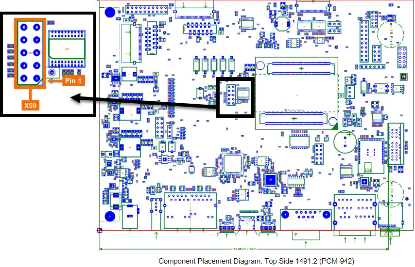
Please note that the PCB version 1491.1 has a different location for the X59 header. In more recent revisions of the carrier board (1491.2) the header was relocated to be closer to the center of the board.
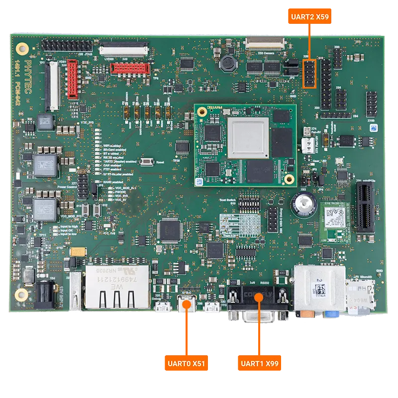
The UART channels correspond to the following connectors and system paths.
Hardware Interface |
Connector |
Sysfs Path |
|---|---|---|
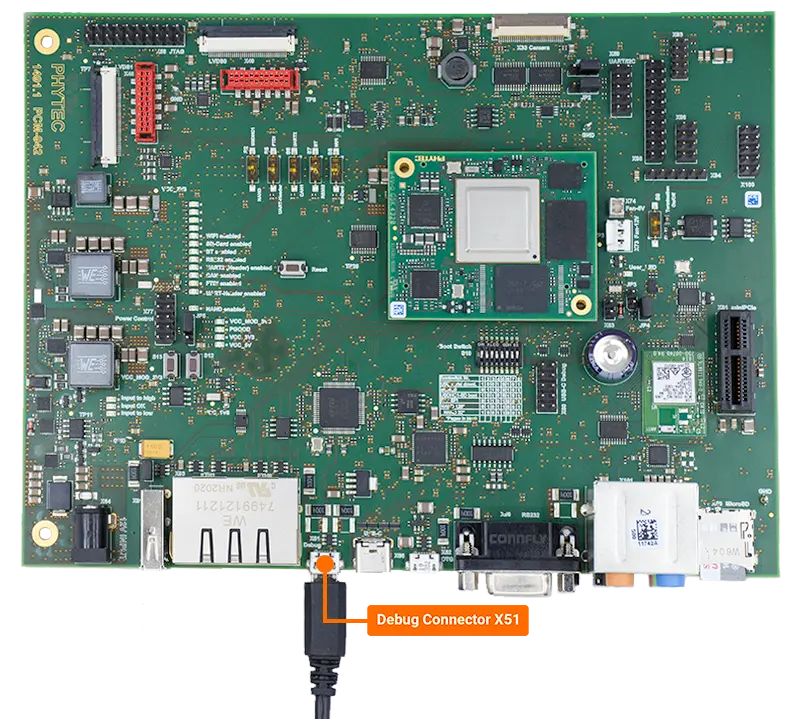
UART0 |
X51 (Micro USB) |
/dev/ttyLP0 |
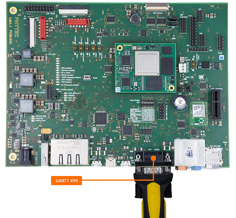
UART1 |
X99 (DB9 - RS232) |
/dev/ttyLP1 |
UART2 |
X59 (General Purpose Header) |
/dev/ttyLP2 |
Note
All of the UART interfaces have muxing options available. Please refer to our Booting Essentials page for more information.
The FTDI device connected to UART0 also provides access to the M40_UART0 through the same connector (not supported in i.MX8X ALPHA1 release). The connector X99 allows for the use of UART1 a General Purpose (GP) UART (ttyLP1), which is translated to RS-232 levels. Note this UART is muxed with BT functionality. The connector X59 allows for the use of UART2 a General Purpose (GP) UART (ttyLP2). Note this UART is muxed with the CAN interface and an overlay must be applied in U-Boot.
Requirements
Micro-USB Cable (Included in kit)
UART0
-
UART1
-
UART2
-
UART2
Hardware Setup
UART0 (Debug)
This is the default communication interface with the development kit.
UART1
UART2
Note
This is not a standard UART and requires the use of female to female jumper wires.
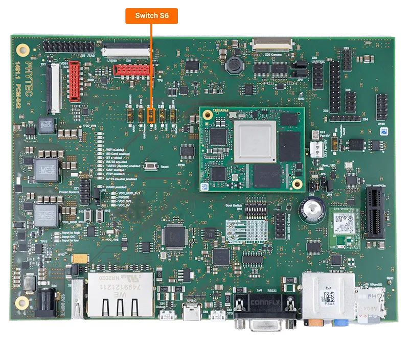
Additionally, UART2 is muxed with the CAN interface through Switch S6 on the carrier board.
Change S6 to UART2
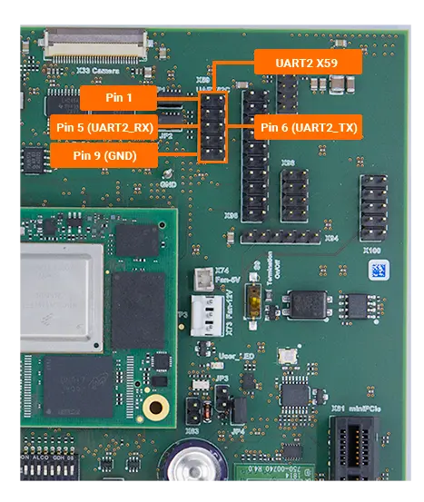
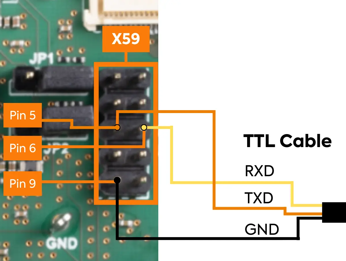
Using female to female jumper wires, connect between the pins of connector X59 and the RS-232 to USB adapter cable using the table and images below. Connect the other end of the RS-232 cable to your host PC.
GND |
Black Connecter |
Pin 9 (X59) |
|---|---|---|
TXD |
Orange Connecter |
Pin 6 (X59) |
RXD |
Yellow Connecter |
Pin 5 (X59) |
With the default console (UART0) connected, power on the kit and stop in U-Boot.
Apply the device tree overlay that enables the UART2 interface. Then boot into Linux.
Target (U-boot)setenv overlay_files phytec-imx8qxp-uart2.dtbo boot
UART1 & UART2 Communication
Open a terminal on your host PC, choose the COM port associated with the UART channel and make sure it has the following port settings.
COM Port Settings Baud Rate
115200
Data
8-bit
Parity
none
Stop Bit
1
Flow Control
none
In Linux setup which UART channel you would like to use (/dev/ttyLP1 or /dev/ttyLP2) and then echo a test message through the UART channel to your other opened terminal.
Target (Linux)stty -F /dev/ttyLP1 115200 echo 'Testing GP UART!' > /dev/ttyLP1
Expected OutputTesting GP UART!
Now set up your default UART0 channel to listen for data from the UART channel you are using (/dev/ttyLP1 or /dev/ttyLP2).
Target (Linux)cat /dev/ttyLP1
Type something into your secondary UART console and hit enter.
UART1 or UART2 Console InputTesting!
Expected OutputTesting!
Use Ctrl+C to stop UART0 from listening for new data.
Enabling UART1 or UART2 as an Additional Serial Console
From the default UART channel (UART0), use system control to enable and start the desired UART channel (/dev/ttyLP1 or /dev/ttyLP2).
Note
Note that this setting will persist between boots but will not affect the default console in U-Boot and Linux.
Enable your desired UART channel in system control.
Target (Linux)systemctl enable serial-getty@ttyLP1.service
Expected OutputCreated symlink /etc/systemd/system/getty.target.wants/serial-getty@ttyLP1.service -> /lib/systemd/system/serial-getty@.service.
Start the service for the UART channel.
Target (Linux)systemctl start serial-getty@ttyLP1.service
You should now see the login prompt on the console linked to your desired UART channel. Type “root” to login.
UART1 or UART2 Console Outputimx8x-phycore-kit login:
Test the console input/output using the echo command.
Target (Linux)echo "hello from ttyLP0" > /dev/ttyLP1
UART1 or UART2 Console Outputhello from ttyLP0
UART1 or UART2 Console Inputecho "hello from ttyLP1" > /dev/ttyLP0
Expected Output (Linux)hello from ttyLP1
Use the following commands to disable the new serial console.
Target (UART1 Linux Console)systemctl stop serial-getty@ttyS4.service systemctl disable serial-getty@ttyS4.service
