SPI
This guide will show you how to test the SPI interface on the phyCORE-i.MX8X development kit carrier board.

Requirements
Female to Female Jumper Wire (1x)
SDHC SD card, at least 8GB for PHYTEC’s TISDK release image (Included in development kit)
Linux Host PC or Virtual Machine (Ubuntu recommended) (Only for Transfering Media from Host)
SD card reader (operational under Linux) (Only for Transfering Media from Host)
Hardware Setup
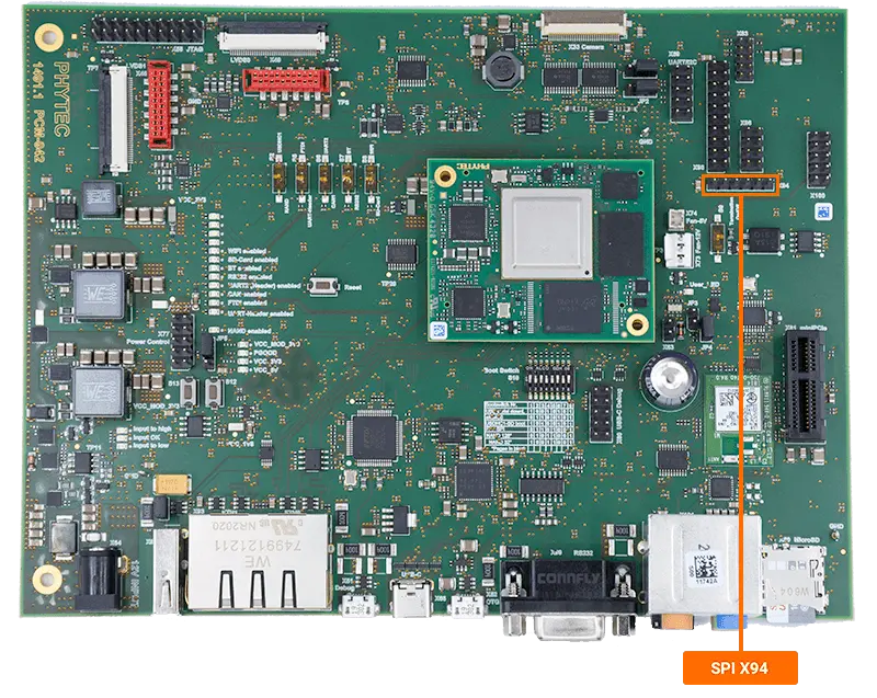
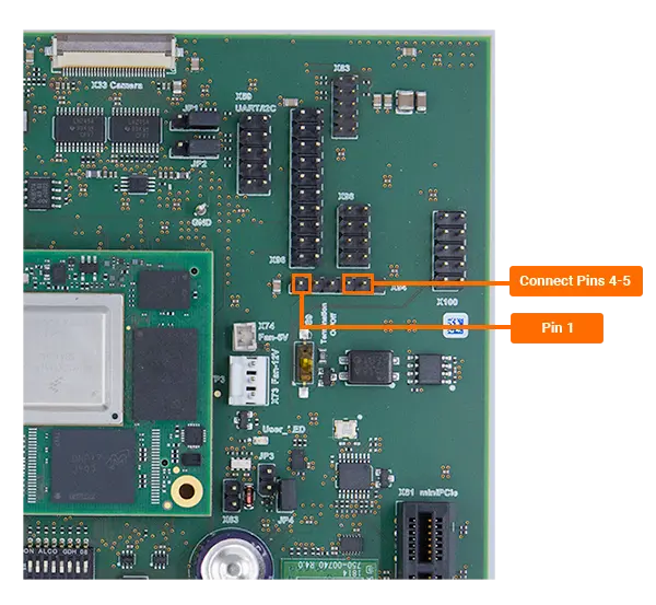
Connect pins 4 and 5 of X94 using a F-F jumper wire. These pins correspond to SPI3’s MISO and MOSI signals

Add the following file into the root directory of the file system that you are booting from.
SD Card “root” Partition Using Ubuntu
Target (Linux)sudo cp spidev_test /media/user/root/home/root/
Plug the SD Card into your development kit, power on, and boot into Linux.
Initiate the loop-back test on the SPI3 interface (/dev/spidev1.0)
Target (Linux)./spidev_test -v -D /dev/spidev1.0
Expected Outputspi mode: 0x0 bits per word: 8 max speed: 500000 Hz (500 KHz) TX | FF FF FF FF FF FF 40 00 00 00 00 95 FF FF FF FF FF FF FF FF FF FF FF FF FF FF FF FF FF FF F0 0D |......@.........................| RX | FF FF FF FF FF FF 40 00 00 00 00 95 FF FF FF FF FF FF FF FF FF FF FF FF FF FF FF FF FF FF F0 0D |......@.........................|
Note
If SPI communication is not functioning properly, only “00”s will be printed in the “rx data”.
This can be demonstrated by running the previous command again with the wire removed.