Configuration Switches
The development kit provides reference circuits for the interfaces available at the SOM connectors. Several IO share pins due to multiplexing and may not be available at the same time. It is likely that you will want to use a signal in a different way than we have chosen on the dev kit. For that reason we added five configuration DIP switches to route interfaces from the SOM to different peripheral connectors. This guide describes how to change and check what interfaces are enabled.
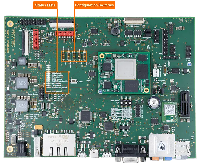
Configuration switches and status LEDs can be found on the carrier board:

The interfaces on the Carrier Board impacted by these switches include:
CAN
NAND
SD Card slot
UART (UART0, M40_UART0, UART1, UART2)
WiFi
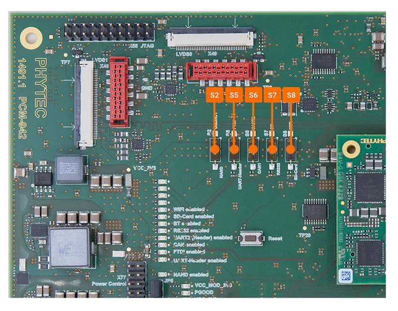
Location and behavior of the Configuration DIP switches is stated below. Switch state should only be modified when no power is applied to the board.

Configuration Switch |
Description |
ON |
OFF |
Notes |
|---|---|---|---|---|
S2 |
SD interface |
SD enabled |
NAND Flash |
Enables connection of USDHC1 off the SOM. NAND flash is not populated by default on the SOM. |
S5 |
Serial Console Type |
FTDI enabled (X51) |
FTDI disabled |
UART0 and M40_UART0 routing to either microUSB or pin header (X59). |
S6 |
UART2 |
UART2 enabled (X59 header) |
CAN enabled (X100 header) |
CAN1 interface |
S7 |
Bluetooth |
Bluetooth enabled |
RS-232 enabled (X99) |
UART1 interface for bluetooth or RS-232 interface. |
S8 |
WiFi |
WiFi enabled |
SD card enabled (X50) |
SDIO interface is shared between WiFi and the SD card slot |