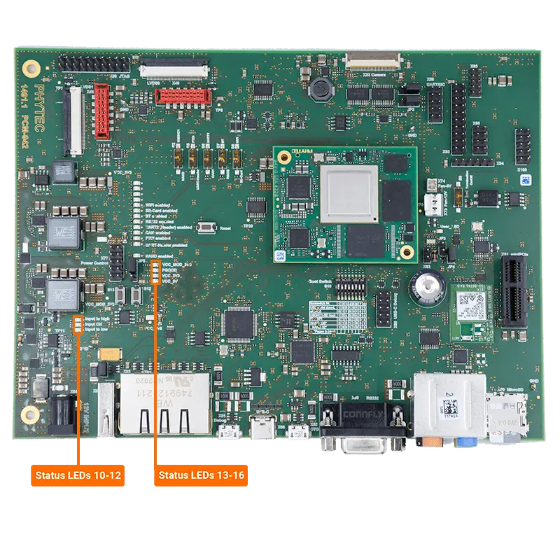
Power LEDS
The phyCORE-i.MX8X Carrier Board has five green LEDs and two red LEDs which indicate the presence of power on the various supply rails available. These LEDs are not user programmable and are present for hardware debugging purposes only.

The table below lists the LEDs and information about their corresponding power rails.
Reference Designator |
Description |
|---|---|
D10 |
Under Voltage Protection Indicator: The UVP Indicator is set to trigger at 11.0V or lower and will not turn off until the voltage returns to 11.9V. |
D11 |
Over Voltage Protection Indicator: The OVP Indicator is set to trigger at 13.5V or higher and will not turn off until the voltage returns to 12.8V. |
D12 |
Input Power Rail Indicator: A over/under voltage protection circuit controls the 12V_IN voltage rail to ensure a proper input voltage to the system |
D13 |
VCC_MOD_3V3 Power Rail Indicator: The switching regulator (U84) powers the VCC_MOD_3V3 power supply rail which powers the SOM. |
D14 |
PGOOD Indicator: Once the input voltage to SOM is stable this signal indicates that the VCC_12V rail is enabled. |
D15 |
VCC_3V3 Power Rail Indicator: The load switch (U50) powers the VCC_3V3 supply rail which powers the various 3V3 accessory circuits on the Carrier Board. |
D16 |
VCC_5V0 Power Rail Indicator: The load switch (U83) powers the VCC_5V0 supply rail which powers the various 5V0 accessory circuits on the Carrier Board. |
Note
The VCC_1V8 rail does not feature an indicator LED:
The adjustable voltage regulator (U60) powers the VCC_1V8 power supply rail which powers the various 1V8 accessory circuits on the Carrier Board.