GPIO
This guide will show you how to connect to toggle a GPIO on the phyCORE-i.MX8X development kit.
Tip
The GPIO pin numbering of the phyCORE-i.MX8X schematic is offset from the device name in sysfs.
You can use the following equation to figure out what number the device is represented as in sysfs.
Hardware Signal = GPIO(Bank)_IO(num)
sysfs GPIO Device = (Bank)*32 + num
Example:
Hardware Signal = LSIO_GPIO0_IO19
sysfs GPIO Device = (0)*32 + 19 = 19
LSIO_GPIO0_IO19 is represented as GPIO19 in sysfs
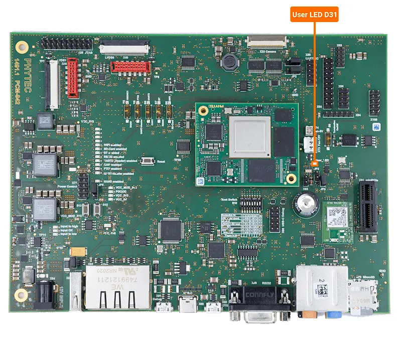
Toggling User LED (D31)
The development kit has a user-configurable LED (D31) that is hooked up to LSIO_GPIO0_IO28 of the processor.
Note
This is named as X_SAI0_TXFS on the SOM schematic and changes to X_USER_LED on the carrier board schematic.

Now that we know the GPIO bank (0) and number (28) we can calculate which gpio to export in software.
(0x32) + 28 = 28
Export GPIO28
Target (Linux)echo 28 > /sys/class/gpio/export
Set GPIO28 as an output
Target (Linux)echo out > /sys/class/gpio/gpio28/direction
Turn ON the User_LED
Target (Linux)echo 0 > /sys/class/gpio/gpio28/value
GPIO Expander (U90)
The GPIO expander is connected to the I2C1 interface at address 0x20 and provides an additional 8 GPIOs that are used for various interfaces such as ETH, the displays, the cameras, and the fan.
To learn how to access the GPIO expander you can refer to our I2C guide.