USB
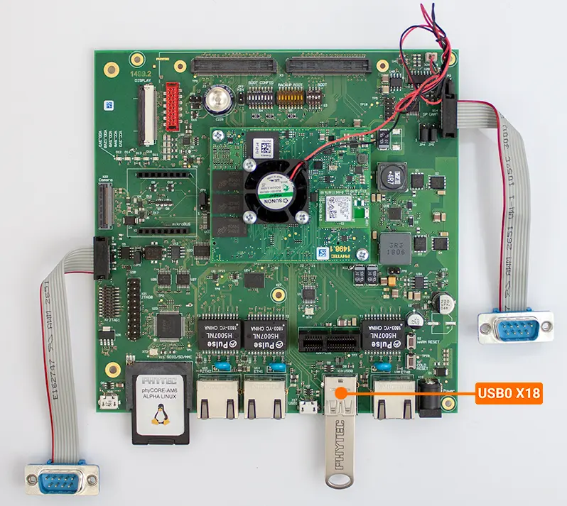
The phyCORE-AM65x development kit brings out USB Host capabilities (USB0) to the Standard-A connector X18 and USB OTG capabilities (USB1) to the Micro-AB connector X17. Connector X18 is USB3.0 compliant and X17 is USB2.0 compliant. This guide will walk you through the use of this interface.
Note
See the end of this guide for further information regarding advanced USB OTG configurations.
USB0
Storage devices formatted with a FAT32 file system, when connected to the USB0 port, are automatically mounted to “/run/media/sda1”.
Note
See the note below if you are not seeing /run/media/sda1 after inserting the USB device in the development kit.
Insert a USB storage device into the X18 connector. The mount point should be sda1 in the directory /run/media/ and this can be confirmed in the printed messages output on the console when the device is registered.
Note
If you did not seeing /run/media/sda1
If the directory /run/media/sda1 doesn’t exist, it is likely due to the flash drive being formatted with either a exFAT or ntfs file system. Both of these will not be recognized by Linux and therefore will not be automatically mounted.
Reformat the Flash Drive to FAT32
WARNING: This process will erase all data on the flash drive. It is highly recommended to back up the contents of the Flash Drive before following these steps.
Connect your Flash Drive to your Windows Host Machine
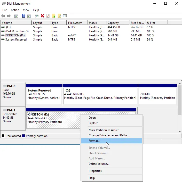
Hit the windows key, type “Disk Management” and then hit Enter.
Right click your flash drive and select “Format”
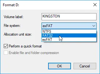
Select FAT32 under File System and then press OK.
Now right click the device in File Explorer and select Eject to safely disconnect the device from your Host Machine.
Generate a random 100 MB file to test writing to and from the storage device.
Target (Linux)dd if=/dev/urandom of=test.file count=100 bs=1M
Copy the file to your storage device and back again:
Target (Linux)dd if=test.file of=/run/media/sda1/test.file bs=1M && dd if=/run/media/sda1/test.file of=test1.file bs=1M
Generate a hash uniquely identifying both the original file and the copied file and ensure they match:
Target (Linux)md5sum test.file && md5sum test1.file
The above command will generate a long and seemingly random string of characters for both files. This long string is called a “hash” and it uniquely identifies the files. If the hash for both files match then you can be confident that both files (down to each bit) are identical.
Expected Outputroot@am65xx-phycore-kit:~# md5sum test.file && md5sum test1.file 83e4656e299c96cf41488bf8b3701bb0 test.file 83e4656e299c96cf41488bf8b3701bb0 test1.file
Be sure to UNMOUNT the drive in software before physically disconnecting it!
Target (Linux)umount /run/media/sda1
USB1
Connect a micro-USB cable between your host computer and the PHYTEC Carrier Board at the micro USB1 connector X17.

Using your Linux console, type the following to load the g_serial module:
Target (Linux)modprobe g_serial
Check that the serial device /dev/ttyGS0 exists:
Target (Linux)ls /dev/tty*
Expected Outputroot@am65xx-phycore-kit:~# ls /dev/tty* /dev/tty /dev/tty19 /dev/tty3 /dev/tty40 /dev/tty51 /dev/tty62 /dev/ttyS6 /dev/ttyp8 /dev/tty0 /dev/tty2 /dev/tty30 /dev/tty41 /dev/tty52 /dev/tty63 /dev/ttyS7 /dev/ttyp9 /dev/tty1 /dev/tty20 /dev/tty31 /dev/tty42 /dev/tty53 /dev/tty7 /dev/ttyS8 /dev/ttypa /dev/tty10 /dev/tty21 /dev/tty32 /dev/tty43 /dev/tty54 /dev/tty8 /dev/ttyS9 /dev/ttypb /dev/tty11 /dev/tty22 /dev/tty33 /dev/tty44 /dev/tty55 /dev/tty9 /dev/ttyp0 /dev/ttypc /dev/tty12 /dev/tty23 /dev/tty34 /dev/tty45 /dev/tty56 /dev/ttyGS0 /dev/ttyp1 /dev/ttypd /dev/tty13 /dev/tty24 /dev/tty35 /dev/tty46 /dev/tty57 /dev/ttyS0 /dev/ttyp2 /dev/ttype /dev/tty14 /dev/tty25 /dev/tty36 /dev/tty47 /dev/tty58 /dev/ttyS1 /dev/ttyp3 /dev/ttypf /dev/tty15 /dev/tty26 /dev/tty37 /dev/tty48 /dev/tty59 /dev/ttyS2 /dev/ttyp4 /dev/tty16 /dev/tty27 /dev/tty38 /dev/tty49 /dev/tty6 /dev/ttyS3 /dev/ttyp5 /dev/tty17 /dev/tty28 /dev/tty39 /dev/tty5 /dev/tty60 /dev/ttyS4 /dev/ttyp6 /dev/tty18 /dev/tty29 /dev/tty4 /dev/tty50 /dev/tty61 /dev/ttyS5 /dev/ttyp7
A device named “PI USB to Serial” should have been detected by your Host Machine. In Windows, Device Manager will indicate which COM port number corresponds to it.
Begin a new serial console using the COM port found in the previous step.
Sending
In the Linux console, enter the following to output a message to the newly opened USB1 console:
Target (Linux)echo "Testing" > /dev/ttyGS0
Verify that the USB1 console printed “Testing”.
Receiving
In the Linux console, enter the following to prepare the phyCORE-AM65x to receive messages from the Host:
Target (Linux)cat /dev/ttyGS0
Now type something into the USB1 console and verify that it outputs to the Linux console.
Enter Ctrl + C in the Linux console to stop waiting for incoming data.
Advanced USB OTG Configurations
JP6 |
OPEN (Default) |
USB OTG Removes the additional 122uF capacitor from USB1 VBUS |
Closed |
USB Host Adds additional 122uF capacitance from USB1 VBUS |
Warning
There are known issues with configuring USB1 to Host Mode at this time. Closing jumper JP6 is not recommended until a later Carrier Board revision.