JTAG
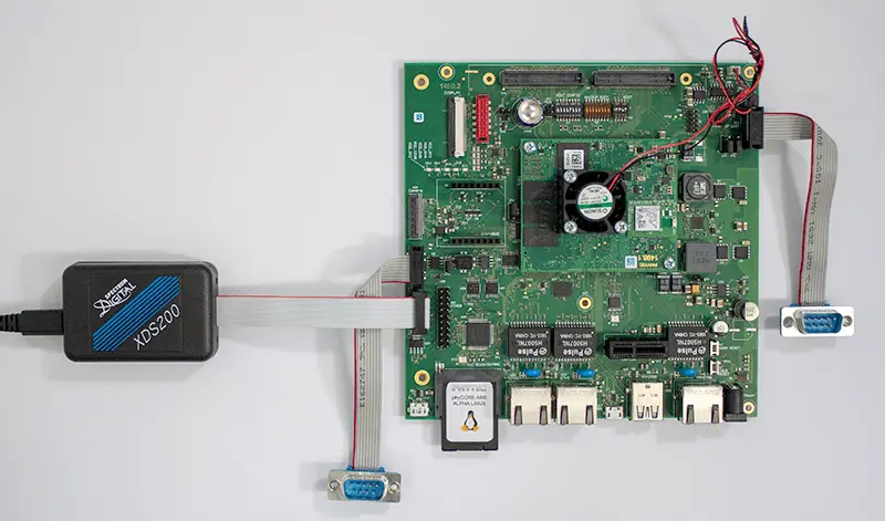
There are two JTAG interfaces on the phyCORE-AM65x development kit (JTAG0 at X21 and JTAG1 at X2). A Spectrum Digital XDS200 USB JTAG Emulator and Code Composer Studio by TI will be needed in order to follow this guide. This guide which will show you how to connect and use these interfaces.
Requirements
Connecting the JTAG Device to the Kit
The phyCORE-AM65x kit has two JTAG connector styles.
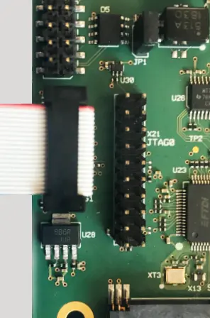
X2 is the smaller notched 20 pin header, X21 is the larger 20 pin connector.
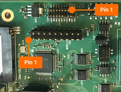
Connect your JTAG Probe to the connector such that the red line on the ribbon cable aligns with pin 1 on the header.
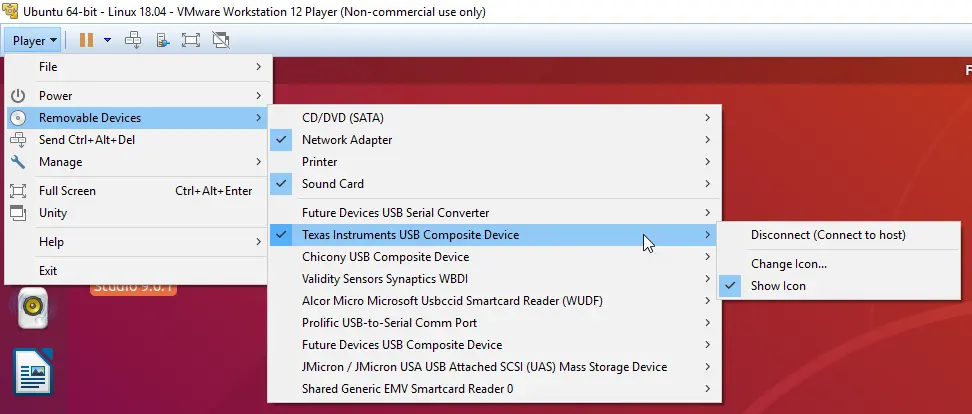
Connecting the JTAG Device to the Host Machine
You may need to connect the JTAG device to your machine if it is not automatically detected.
Creating a New phyCORE-AM65x project in Code Composer Studio
In order to test the JTAG connection, a new project needs to be created in CCS for the phyCORE-AM65x.
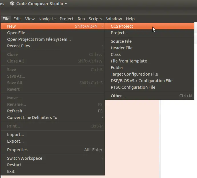
Click on File → New → CCS Project
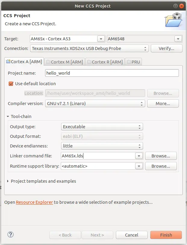
The “New CCS Project” window will appear and you can change the following settings to match what is below.
Target: AM65x - Cortex A53 → AM6548
Connection: Texas Instruments XDS2xx USB Debug Probe
Project name: hello_world
Compiler version: GNU v7.2.1 (Linaro)
Tool-chain → Linker command file: AM65x.lds
Click Finish when everything is configured properly
Creating a New Target Configuration
Now that the project is created, edit the target configuration which will allow you to test the JTAG connection.
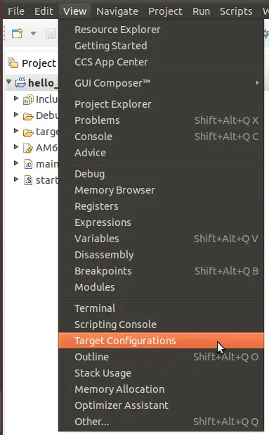
View → Target Configurations
In the Target Configurations windows, you will be able to open up the project configuration file:
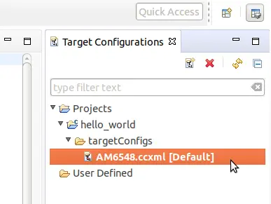
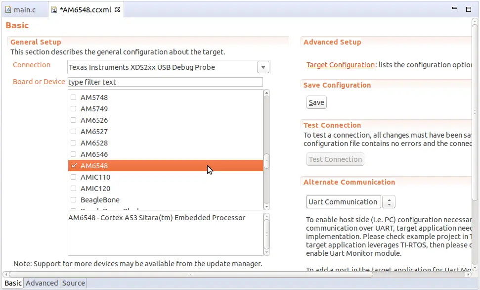
In the target configuration file, select the following options:
Connection → Texas Instruments XDS2xx USB Debug Probe
Board or Device → AM6548
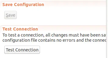
Click the “Save” button when you have the correct configuration options selected
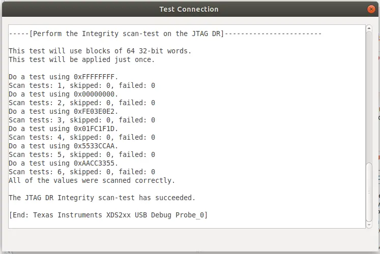
In the same window you will now be able to click on Test Connection
When the device is properly connected, you will see output similar to the example below: