CAN
The CAN module on-board the phyCORE-AM65x SOM supports both the classical CAN and Full CAN FD (CAN with Flexible Data-Rate) protocols. The development kit breaks out the MCAN0 (X_MCU_MCAN0) interface to the X15 header for general use. Depending on the muxing options, a second CAN interface (CAN 2.0B and CAN FD) can be made available through the expansion port X3.
Requirements
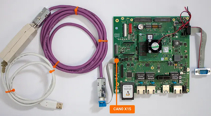
This guide will walk through the basic usage of the CAN interface by transferring data to and from a host PC. In order to follow this guide you will need a CAN-USB adapter cable, the necessary driver for this adapter, and software for your host machine to display the received messages. This guide was tested and written using the following product and software:
Note
See the end of this guide for further information regarding advanced CAN configurations.
Setup the CAN Interface
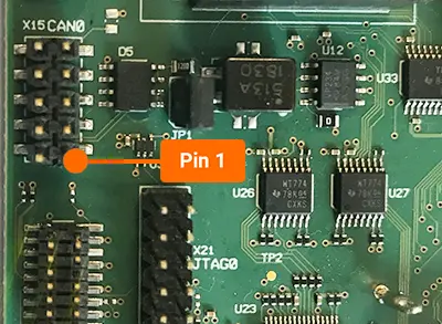
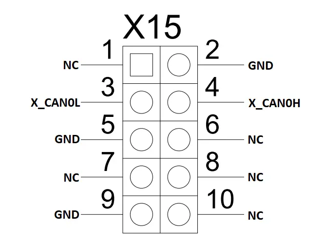
Connect the D-sub 9 ribbon cable to the X15 connector (red line on the cable indicates Pin 1).
Pin 1 location on phyCORE-AM65x development kit
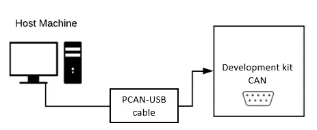
Connect the PCAN-USB adapter between the host PC (USB port) and the CAN0 interface (X15) on the development kit.
Set up the Host PC with PCAN-View
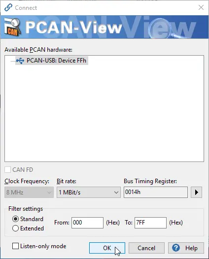
Open PCAN-View on your host PC and select the device from the available hardware. Set the Bit rate field to 1 MBit/s and click OK.
Note
If you cannot find your device in the listed hardware, ensure that you have the correct driver installed on your host PC. You can obtain the driver online from the Downloads section here or directly here.
In the phyCORE-AM65x Linux console, use the following commands to set up the CAN interface and configure the bit rate. For this example 1 MBit/s is used.
Target (Linux)ip link set can0 down ip link set can0 up type can bitrate 1000000 ip link set can0 up
Send CAN messages
In this example you will test data transfer from the phyCORE-AM65x kit to the host PC.
Make sure PCAN View is open on your host PC
Enter the following on the phyCORE-AM65x console to send data on the CAN bus.
Target (Linux)cansend can0 000#DE.AD.BE.EF.CA.FE.BA.BE
In PCAN-View verify that the data is correct in the “Receive” window.
Receive CAN Messages
In this example you will test data traveling in the opposite direction - from the host PC to the phyCORE-AM65x kit.
Enter the following command on the phyCORE-AM65x console to put the CAN interface into listening mode:
Target (Linux)candump can0
On your host PC in PCAN-View, create a new transmit message.
Enter DEADBEEFCAFEBABE as the data (hex)
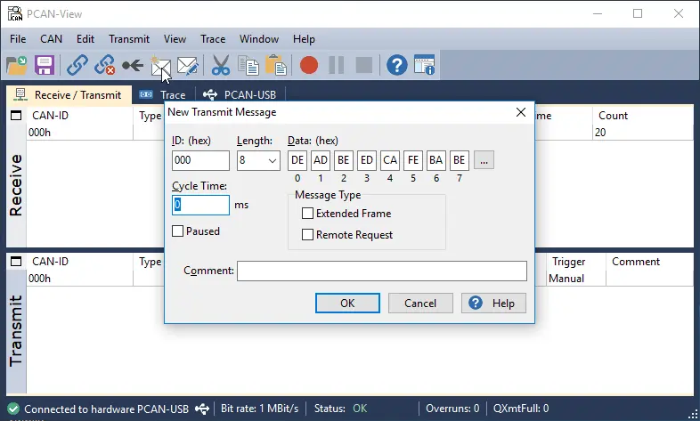
Select the message. You can press the space-bar a few times to send the message more than once.
On the phyCORE-AM65x console you should see that the message has been received.
Expected Outputroot@am65xx-phycore-kit:~# candump can0 can0 000 [8] DE AD BE ED CA FE BA BE
To exit listening mode on the phyCORE-AM65x enter Ctrl + C to stop candump.
Advanced CAN References
Reference Designator |
Jumper Settings |
Description |
|---|---|---|
JP1 |
Open |
Remove 120Ω termination between X_CAN0H and X_CAN0L |
JP1 |
Closed (Default) |
Add 120Ω termination between X_CAN0H and X_CAN0L |
Note
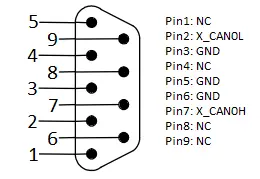
The adapter cable included with the phyCORE-AM65x development kit does not have the same numbering scheme as the pins at the header X15.