OLDI Display
Warning
There is a known issue with the device tree in the BSP-Yocto-TISDK-AM65xx-ALPHA1 release where the LCD-018 display is not properly enabled. Please see the Known Issues page for more information and a workaround.
The phyCORE-AM65x Carrier Board provides support for an OLDI LVDS display through the connector X24, which is comprised of an LVDS signal connector (white) and a power connector (red). These connectors support various PHYTEC LCDs, such as the LCD-018-070-KAP.
The development kit also provides a touch controller (STMPE811) at U39 and interfaces the resistive touch panel typically integrated into an LCD. Communication to and from this touch controller is accomplished with I2C and its device address which is configurable via the J8 jumper.
This guide explains how to connect an OLDI LVDS display to the phyCORE-AM65x development kit and access it in Linux.
Note
See the end of this guide for further information regarding advanced touch controller configurations.
Requirements
Setting up the Display
Display Switches
Please Read
There is a switch labeled “S1” on the back of LCD-018 where the backlight can be set to either: “always on”, “always off”, “PWM”, or “potentiometer” (there is a potentiometer on the display labeled R30). In order to control the backlight via the phyCORE-AM65x as described in this guide, this switch needs to be set to PWM which corresponds to | off | off | on | off |
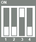
There is a switch labeled “S2” on the back of the LCD-018 that specifies the I2C address of the EEPROM on board the display. To ensure the address of the display EEPROM doesn’t conflict with any other devices on the same bus (RTC and EEPROM on the SOM) this switch needs to be set to | on | on | off | on |

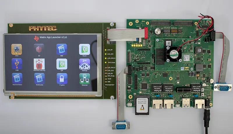
With the board powered off, connect the display to the connector on the phyCORE-AM65x Carrier Board as shown in the picture.
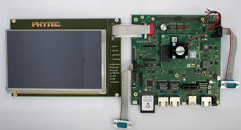
Power on the phyCORE-AM65x and boot into Linux. (You may need to calibrate the LCD). An application will start.
Controlling Display Backlight
The backlight brightness of the display is controlled by a PWM and can be configured via Linux sysfs.
Read current brightness: (Expected output is a numeric value between 0-7)
Target (Linux)cat /sys/class/backlight/display_backlight/brightness
Set “brightness” to values 0-7, with 7 being the brightest. For example:
Target (Linux)echo 7 > /sys/class/backlight/display_backlight/brightness
Set bl_power to turn backlight off/on. Valid values are 0-4:
Level |
Name |
Power |
|---|---|---|
0 |
= FB_BLANK_UNBLANK |
Backlight fully enabled |
1 |
= FB_BLANK_NORMAL |
|
2 |
= FB_BLANK_VSYNC_SUSPEND |
|
3 |
= FB_BLANK_HSYNC_SUSPEND |
|
4 |
= FB_BLANK_POWERDOWN |
Backlight powered down |
Use the following command to check the state of the backlight:
Target (Linux)cat /sys/class/backlight/display_backlight/bl_power
The backlight is on by default:
Expected Outputroot@am65xx-phycore-kit:~# cat /sys/class/backlight/display_backlight/bl_power 0
Power off the display:
Target (Linux)echo 4 > /sys/class/backlight/display_backlight/bl_power
Power the display back on:
Target (Linux)echo 0 > /sys/class/backlight/display_backlight/bl_power
Tip
Not seeing the display brightness change? Ensure you have the switch “S1” correctly set on the back of the LCD. See the above “Setting up the Display” section regarding the display switch settings.
Display Touchscreen
The LCD-018 has an on board capacitive touch screen controller that is controlled by the phyCORE-AM65x via I2C. You can use the touchscreen to interact with the application running on the display. This section provides some additional information on the touchscreen implementation in Linux.
By default, input0 corresponds with the touchscreen controller in the phyCORE-AM65x Linux BSP. However, if additional input devices have been added, this could be different. Confirm that the name of input0 matches the touchscreen controller’s with the following command:
Target (Linux)cat /sys/class/input/event0/device/name
Expected Outputroot@am65xx-phycore-kit:~# cat /sys/class/input/event0/device/name EP0700M09
We can see here that the name of the input0 interface is named “EP0700M09”.
Use the input-events command to print out additional information when the touch screen is pressed:
Target (Linux)input-events 0
Expected Output/dev/input/event0 bustype : BUS_I2C vendor : 0x0 product : 0x0 version : 0 name : "EP0700M09" bits ev : EV_SYN EV_KEY EV_ABS waiting for events 18:02:52.959948: EV_ABS ??? 0 18:02:52.959948: EV_ABS ??? 297 18:02:52.959948: EV_ABS ??? 855 18:02:52.959948: EV_KEY BTN_TOUCH pressed 18:02:52.959948: EV_ABS ABS_X 297 18:02:52.959948: EV_ABS ABS_Y 855 18:02:52.959948: EV_SYN code=0 value=0 18:02:52.965230: EV_ABS ??? 294 18:02:52.965230: EV_ABS ??? 852 18:02:52.965230: EV_ABS ABS_X 294 18:02:52.965230: EV_ABS ABS_Y 852 18:02:52.965230: EV_SYN code=0 value=0 18:02:52.979243: EV_ABS ??? 292 18:02:52.979243: EV_ABS ABS_X 292 18:02:52.979243: EV_SYN code=0 value=0 18:02:52.993009: EV_ABS ??? 851 18:02:52.993009: EV_ABS ABS_Y 851 18:02:52.993009: EV_SYN code=0 value=0 18:02:53.006912: EV_ABS ??? 291 18:02:53.006912: EV_ABS ??? 852 18:02:53.006912: EV_ABS ABS_X 291 18:02:53.006912: EV_ABS ABS_Y 852 18:02:53.006912: EV_SYN code=0 value=0 18:02:53.020058: EV_ABS ??? 289 18:02:53.020058: EV_ABS ??? 856 18:02:53.020058: EV_ABS ABS_X 289 18:02:53.020058: EV_ABS ABS_Y 856 18:02:53.020058: EV_SYN code=0 value=0 18:02:53.025591: EV_ABS ??? -1 18:02:53.025591: EV_KEY BTN_TOUCH released
Use CTRL + C to cancel the print command
Advanced Touch Controller Configurations
J8 |
1+2 (Default) |
Sets the U39 LVDS Touch Controller I2C address to 0x82 |
2+3 |
Sets the U39 LVDS Touch Controller I2C address to 0x88 |