PWM
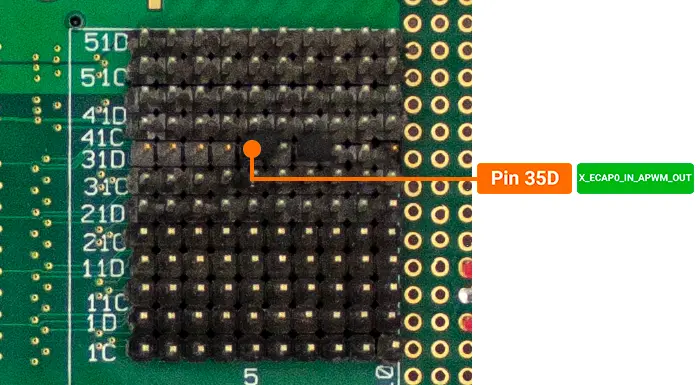
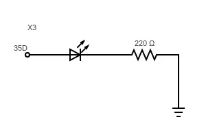
The phyCORE-AM65x SOM brings out a selection of GPIOs that can be muxed to output a PWM signal. On the development kit you can access one of these signals through the PHYTEC Expansion board (PCM-957) at pin 35D. This guide walks through the basic steps of exporting this channel, configuring it, and enabling it to control the brightness of an LED.
Signal Name |
Expansion Board Pin # |
Description |
|---|---|---|
X_ECAP0_IN_APWM_OUT |
35D |
3.3V PWM Channel |
Warning
The signal X_ECAP0_IN_APWM_OUT is used for OLDI backlight display by default. Disconnect the display when using this PWM for other purposes.
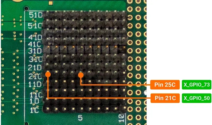
Set up Hardware Configuration
Set up Software Configuration
In order to be accessible in Linux, the PWM channels need to be configured in the Linux device tree. PHYTEC has provided a sample device tree overlay in the boot directory of the root file system which configures expansion connector interfaces used in this Peripheral Guide. To enable this device tree overlay:
The device tree overlay is set in U-Boot.
To enter U-Boot, hit any key within 3 seconds of powering on the hardware to halt autoboot.
Clear the “default_overlays” variable and modify the “extra_overlays” variable to point to the sample dtbo: “k3-am65xx-phytec-expansion-sample.dtbo”. The “default_overlays” variable needs to be cleared because it is set to k3-am65xx-phytec-lcd-018.dtbo which conflicts with the sample.
Target (U-Boot)setenv default_overlays setenv extra_overlays k3-am65xx-phytec-expansion-sample.dtbo saveenv
To exit U-Boot and continue booting into Linux, type boot
Target (U-Boot)boot
Warning
The Expansion Sample overlay k3-am65xx-phytec-expansion-sample.dtbo conflicts with the LCD-018 overlay due to the PWM being used for backlight in the LCD-018. Make sure to disconnect the display when using this overlay before powering on the development kit.
Access PWM in Linux
To request a PWM channel from the kernel, write a 0 to the export attribute:
Target (Linux)echo 0 > /sys/class/pwm/pwmchip0/export
The duty cycle and period are set to 0 by default. You will need to configure these before enabling the PWM channel:
Target (Linux)echo 1000000 > /sys/class/pwm/pwmchip0/pwm0/period echo 100000 > /sys/class/pwm/pwmchip0/pwm0/duty_cycle
Note
The duty cycle and period attributes are expressed in nanoseconds (10-9 seconds). For this example we are using a period of 1 ms with a duty cycle of .1 ms which is the same as saying our signal is at 1 kHz with a 10 percent duty cycle.
Enable the channel:
Target (Linux)echo 1 > /sys/class/pwm/pwmchip0/pwm0/enable
You should now see that the LED is very dim. To increase the brightness, you must increase the duty cycle. The following command changes the duty cycle to 50%.
Target (Linux)echo 500000 > /sys/class/pwm/pwmchip0/pwm0/duty_cycle
The following command increases the duty cycle to 90%.
Target (Linux)echo 900000 > /sys/class/pwm/pwmchip0/pwm0/duty_cycle
Disabling the Channel
Target (Linux)echo 0 > /sys/class/pwm/pwmchip0/pwm0/enable
Un-Exporting the Channel
Target (Linux)echo 0 > /sys/class/pwm/pwmchip0/unexport
Revert to the Default Software Configuration
This guide requires disabling the LCD-018 and enabling a sample expansion overlay. In order to revert back to the default overlay settings, the following needs to be run in U-Boot:
To enter U-Boot, hit any key within 3 seconds of powering on the hardware to halt autoboot.
Target (U-Boot)env default -f -a saveenv
~