I2C
The phyCORE-AM65x SOM supports up to six I2C interfaces. This guide provides information on how to view, access, and interact with the I2C interfaces on the Linux development kit.
I2C devices
The six I2C interfaces will show up in Linux as the corresponding devices:
Hardware Interface |
sysfs Path |
|---|---|
I2C0_WKUP |
/dev/i2c-0 |
I2C0_MCU |
/dev/i2c-1 |
I2C0 |
/dev/i2c-2 |
I2C1 |
/dev/i2c-3 |
I2C2 |
/dev/i2c-4 |
I2C3 |
/dev/i2c-3 |
I2C0 Devices
The I2C0 (/dev/i2c-2) interface is heavily utilized on the phyCORE-AM65x development kit. Devices on board the SOM such as EEPROM and RTC are connected on this bus. In addition, on the development kit Carrier Board, this bus is used for the touch screen controller.
Use i2cdetect from Linux to scan the bus for devices:
Target (Linux)i2cdetect -y -r 2
This command outputs the address of all devices on the bus. You should see something similar to the below:
Expected Outputroot@am65xx-phycore-kit:~# i2cdetect -y -r 2 0 1 2 3 4 5 6 7 8 9 a b c d e f 00: -- -- -- -- -- -- -- -- -- -- -- -- -- 10: -- -- -- -- -- -- -- -- -- -- -- -- -- -- -- -- 20: -- -- -- -- -- -- -- -- -- -- -- -- -- -- -- -- 30: -- -- -- -- -- -- -- -- -- -- -- -- -- -- -- -- 40: -- -- -- -- -- -- -- -- -- -- -- -- -- -- -- -- 50: UU -- 52 -- -- -- -- -- 58 -- -- -- -- -- -- -- 60: -- -- -- -- -- -- -- -- -- -- -- -- -- -- -- -- 70: -- -- -- -- -- -- -- --Note
UU indicates that the device connected is tied to a driver. You will be unable to talk to this device via i2c command (i2cset and i2cget).
These detected interfaces match with the devices connected to I2C0 on the development kit.
Interface |
Address |
Description |
|---|---|---|
EEPROM |
0x51 (0x58) |
4kB EEPROM on the SOM (EEPROM Guide) |
RTC |
0x52 |
External RTC on the SOM (RTC Guide) |
Get Fancy!
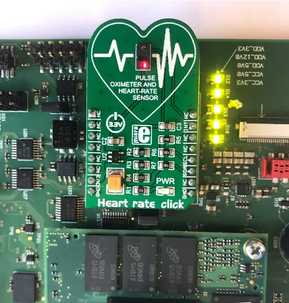
For this simple demo we will be using the Heart Rate Click by MIKROE.

The Heart Rate Click is capable of monitoring heart rates and measuring pulse oximetry! However, in this demo we will not be making full use of this sensor and will instead explore basic functionality of its integrated temperature reading capabilities (this is provided for calibrating SpO2 readings). By communicating with the sensor directly over I2C (using a bash script) we can demonstrate how to set registers within the MAX30100 sensor to configure it to perform an action (like measuring the temperature). Once the sensor has completed it’s task we can again access the registers within the sensor to retrieve the result.
Connect the Heart Rate Click to the mikroBUS Socket X8 on the Carrier Board. It is important to connect the click board in the exact same orientation as in the photo below.
Enter the following command in the Linux console to open a text editor (this will create a new document in the root directory named Temp.sh) :
Target (Linux)vi ~/Temp.sh
Enter the following and save the file (mikrobus on different I2C, code block needs updating):
Tip
The vi text editor begins in “Command Mode” and you must first hit the ‘i’ key in order to enter “Insert Mode”. Using the arrow keys to navigate, make the necessary changes and then hit ESC to go back to “Command mode”. Now enter “:wq” to write the file and quit.
Pro Tip: Use the right click on your mouse to paste! This will only work if you are in “Insert Mode” first.
  #!/bin/bash

  #echo Input HR bus:
  #read -r bus
  #echo Input HR address:
  #read -r addy

  bus=0x02
  addy=0x57

  MX=0.0625

  echo "Reading Temp..."

  i2cset -y "$bus" "$addy" 0x06 0x03      #HR/SPO2 mode
  i2cset -y "$bus" "$addy" 0x09 0x22      #LED bias 7.6mA
  i2cset -y "$bus" "$addy" 0x06 0x0b      #Start a temp reading

  sleep 1                                 #Give the MAX30100 some time to record the reading
                                          #the sensor does have interupt capabilites that could
                                          #tell us when the reading is complete but this is far simpler

  T_int=$(i2cget -y "$bus" "$addy" 0x16)  #Read the integer register
  T_fra=$(i2cget -y "$bus" "$addy" 0x17)  #Read the fractional register
  T_int=$((T_int))                        #Convert from Hex to base-10
  T_fra=$((T_fra))
  temp="$(echo "$T_fra*$MX" | bc)"        #Multiply the fractional reading by the constant (refer to MAX30100 DataS

  echo $(echo $temp + $T_int | bc)        #Add and echo the final result in C
Change the permissions such that you can execute the script:
Target (Linux)chmod a+x ~/Temp.sh
Place a finger or thumb in the center of Heart Image on the Click Board.
Enter the following command while holding your finger on the sensor:
Target (Linux)./Temp.sh
Note
The human body should be around 37C at its core. It will be normal for the sensor to read somewhat below this when measuring temperature on a finger or thumb.
Due to the mikroBUS’ close proximity to the SOM, it is also normal for this to read above room temperature when taking a reading without a finger on the sensor.