JTAG
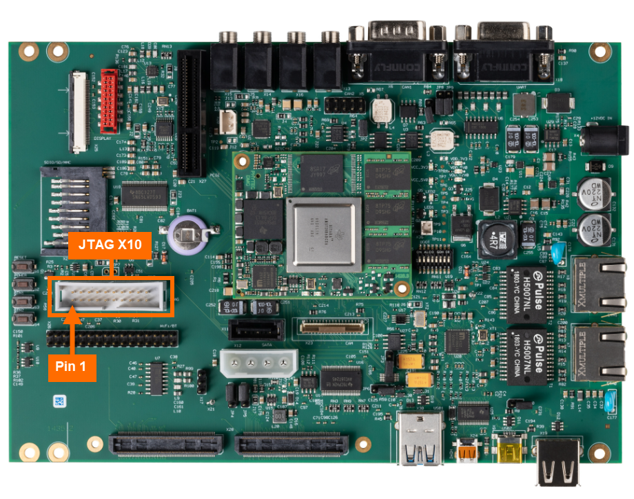
There is one JTAG interface on the phyCORE-AM57x that is accessible at the 20-pin header X10. This guide which will show you how to connect to and verify the onboard XDS200 USB JTAG debugger via a connection integrity test executed using TI’s Code Composer Studio IDE. To learn more information about the phyCORE-AM57x JTAG debug interface, please see section 24 in the Hardware Manual.
Requirements
-
CCS12.4.0.00007
Hardware Setup
Power off the kit and remove power.
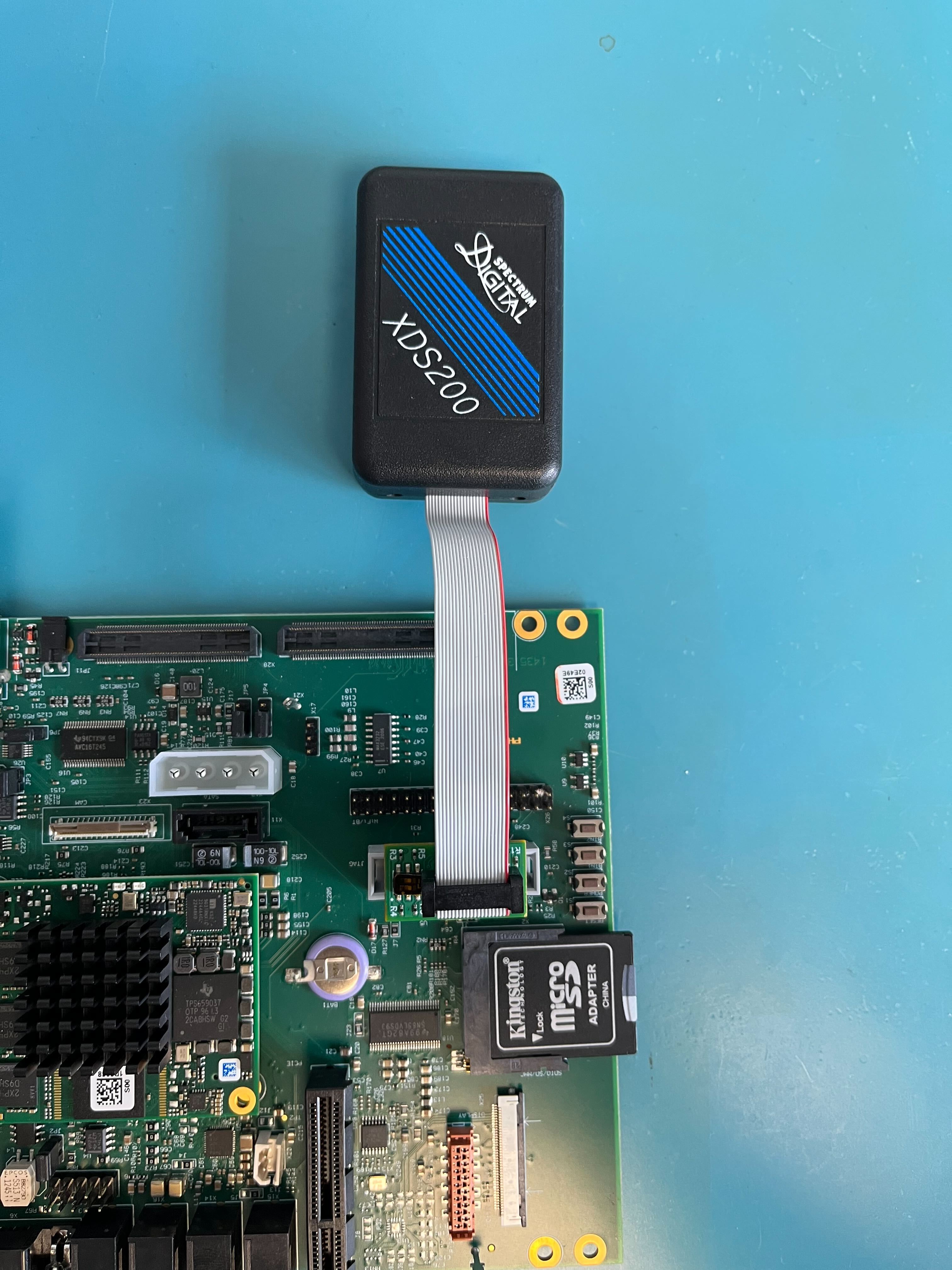
Connect the JTAG probe to the connector such that the red line on the ribbon cable aligns with pin 1 on the header.
Power on the kit.
Host Setup
Download the latest CCSTUDIO installer for your Windows host machine.
Note
You could install this for your Linux VM however it is recommended to install this into the native OS of your Host Machine to avoid dealing with USB pass through related issues. PHYTEC generally runs native Windows machines and then hosts Linux build systems as a VM or on remote servers.
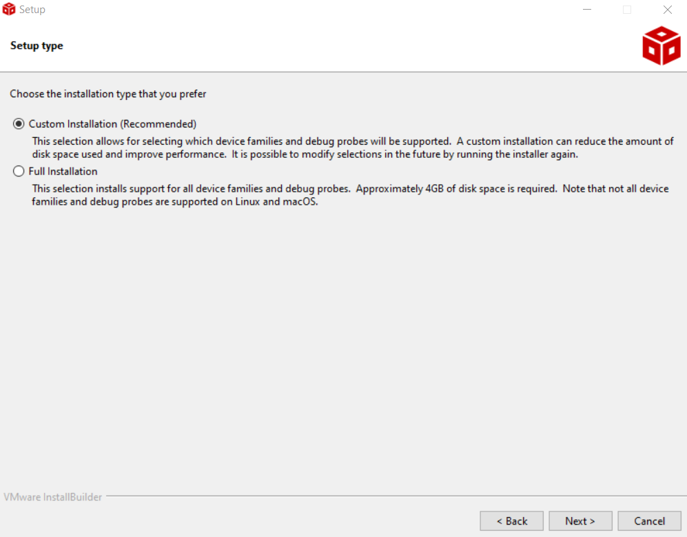
As you work through the installer prompts:
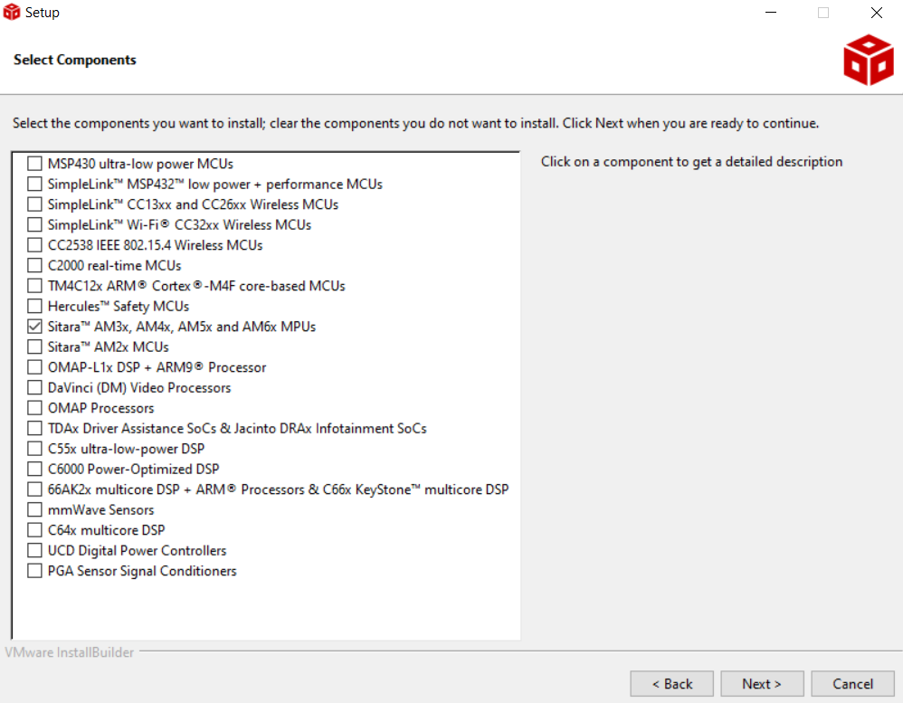
Select the Custom Installation Setup Type:
When prompted to Select Components, enable Sitara AM3x, AM4x, AM5x and AM6x MPUs.
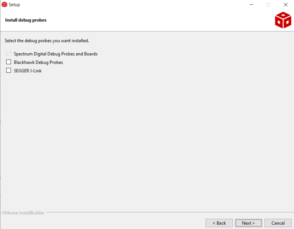
When prompted to Install debug probes, ensure that the Spectrum Digital Debug Probes and Boards option is selected (should be done by default but will depend on the version CCS being installed):
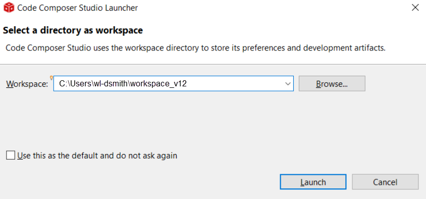
Create a new workspace (it is recommended to choose a workspace directory without any spaces in the path, we at PHYTEC have experienced issues with the Sitara SDKs when it comes to their build scripts and spaces in paths).
Note
The following Workspace location is just an example, the default location for you will probably reflect the user you are logged in as.
Once CCS has launched navigate to View Target Configurations.
Right-click inside the Target Configurations pane and select New Target Configuration.
Name the configuration AM57x_XDS200_USB.ccxml
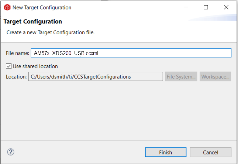
Set the connection to Texas Instruments XDS200 USB Debug Probe and the Device to AM5728x.
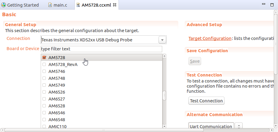
Hit the Save Configuration button.
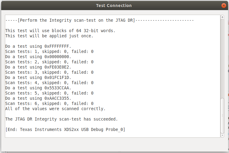
Now you can hit the Test Connection button. You should see a few tests run and complete successfully, including a reset of the processor and integrity scans.