Camera
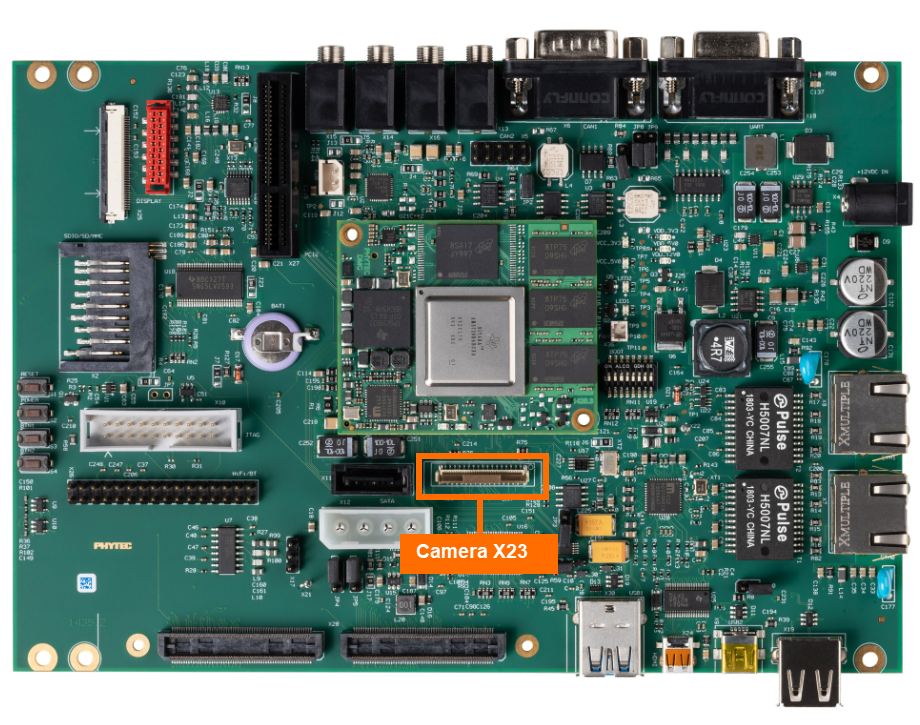
The phyCORE-AM57x development kit provides access to an 8-bit parallel camera at connector X23. Data and control signals are transmitted in parallel via a 33-pin FFC cable. This minimizes the interface effort and still enables compatibility of the camera types. This guide will walk through the basic validation of this camera interface by utilizing a GStreamer Pipeline to feed video captured by the camera to the LCD-018 display. For more information on the Camera interface, please see section 28 in the Hardware Manual.
Note
The PCM-057-10203111I SOM, featuring the AM571X SoC, does not support the camera.
Requirements
LCD-018-070-KAP
7” LVDS Capacitive Touch Display
Note
Be sure that you are not using a headless BSP image as this does not support the display interface. See BSP-Yocto-AM57x-PD23.1.1 for more information.
Hardware Setup
Note
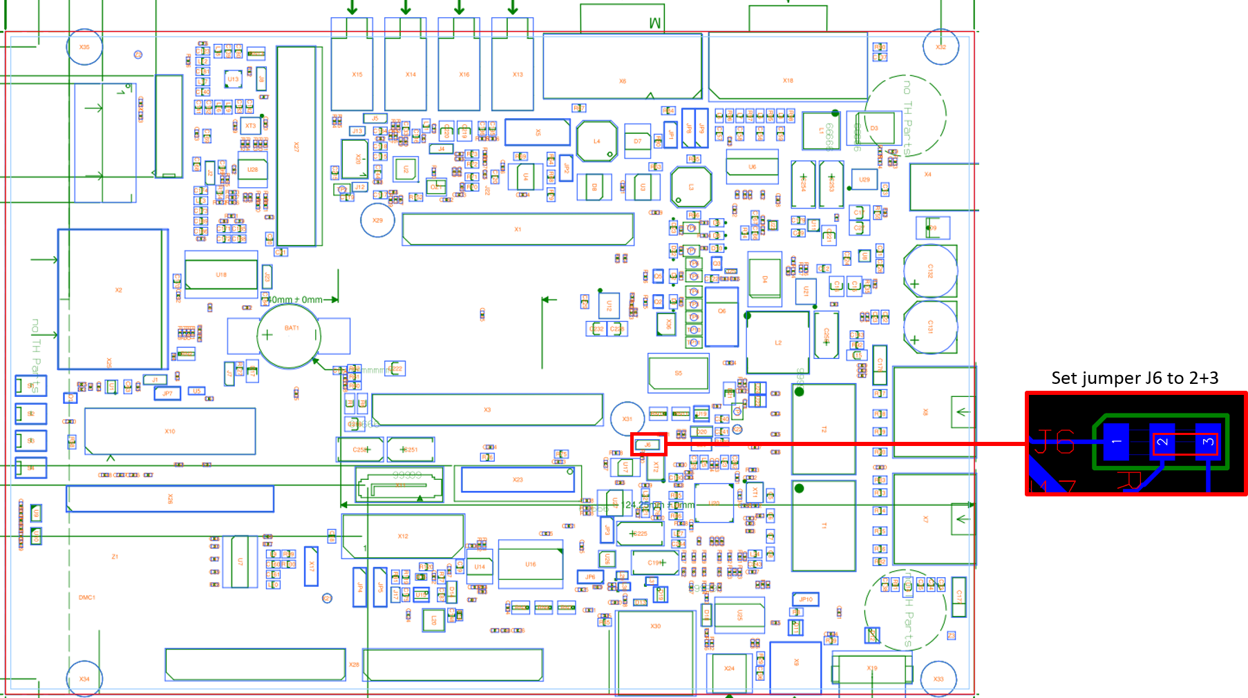
Carrier Board PCB revision 1435.2 can be used if solder jumper J6 is set to position 2+3.
With the development kit powered off and the power supply removed, connect the phyCAM-P camera to the carrier board using the supplied ribbon cable to connector X23.
Open the X23 connector by pushing the dark brown tab upwords.
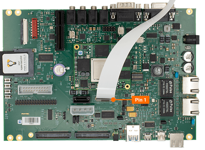
Insert the ribbon cable into the connector, with the blue tape facing away from the SOM. Meaning pin 1 of the carrier board should match up with pin 33 of the camera.
Once the ribbon cable has been seated into the connector, pull the dark brown tab down.
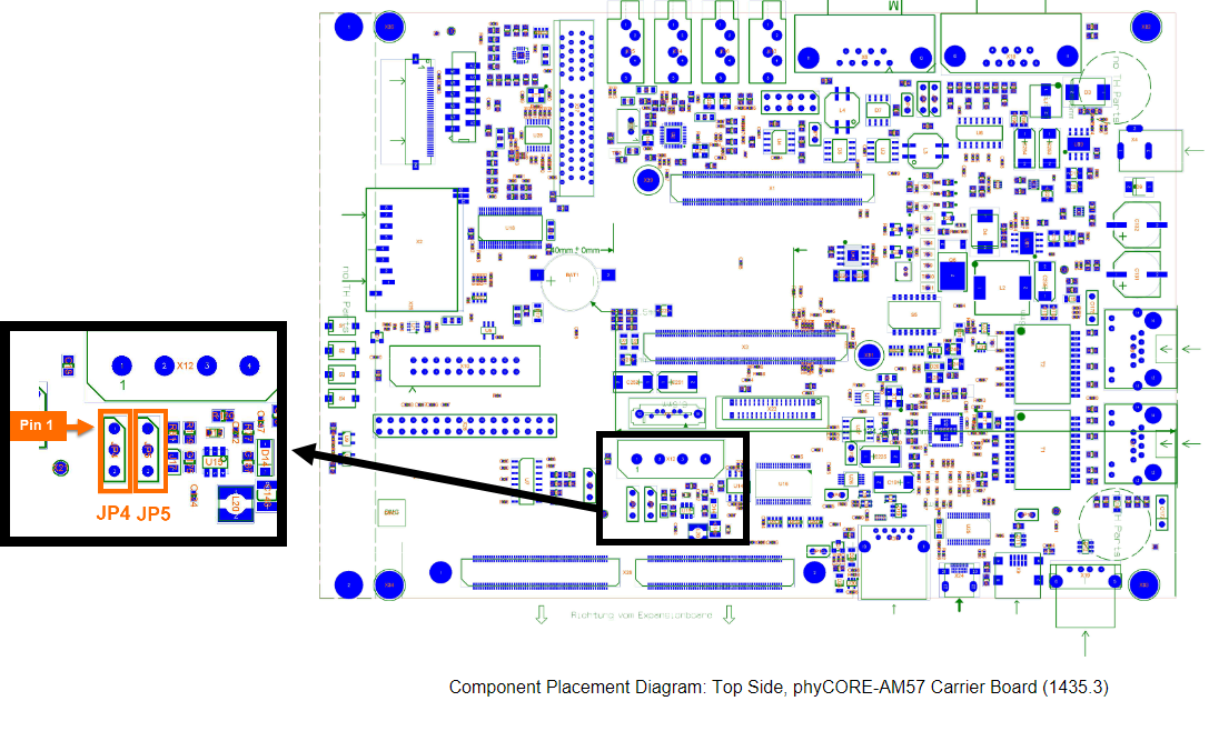
When working with the VM-016 camera model, verify that the JP4 and JP5 jumpers are both set to the 2+3 position.
Verify that the DIP switches (S1) on the back of the LCD-018 are set to backlight to use the PWM setting.
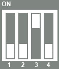
Note
The backlight can be set to either: “always on”, “always off”, “PWM”, or “potentiometer”. See the Display guide for more information.
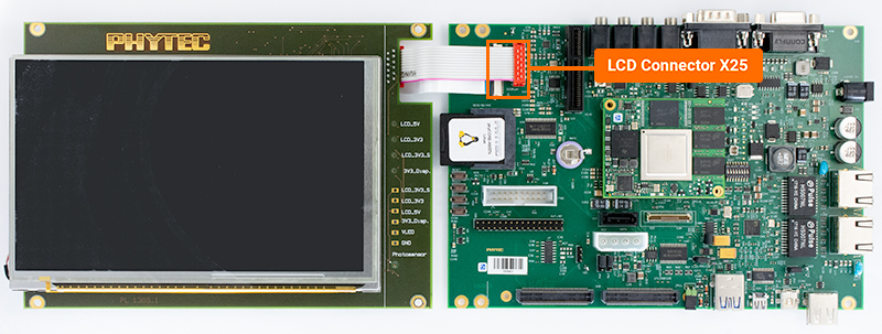
Connect the display to the connectors at X25.
Open the X25 connector by gently pulling the black tab toward the edge of the board.
Insert the ribbon cable into the connector, with the blue tape facing up.
Once the ribbon cable has been seated into the connector, pull the black tab back towards it’s closed position.
The red connector should be a standard push in connection.
Taking a Video
Stop the qtdemo and weston demos.
Target (Linux)systemctl stop phytec-qtdemo systemctl stop weston.socket
Now take the video feed from the camera and output it to the display:
Target (Linux)gst-launch-1.0 v4l2src device=/dev/video1 num-buffers=1000 io-mode=4 ! 'video/x-bayer, format=grbg, width=(int)1280, height=(int)800,framerate=30/1' ! bayer2rgb ! kmssink sync=false
Note
The above command will only work for the VM-016, if you are using a VM-009, you will need to use the command:
gst-launch-1.0 v4l2src device=/dev/video1 num-buffers=1000 io-mode=4 ! 'video/x-raw, format=(string)YUY2, width=(int)1280, height=(int)1024' ! vpe num-input-buffers=8 ! queue ! kmssink
The camera feed should be displayed on the LCD. Use Ctrl + C to stop.
Taking a Picture
To capture a JPG picture named “smile.jpg”, use the following gstreamer pipeline command.
Target (Linux)gst-launch-1.0 v4l2src num-buffers=5 device=/dev/video1 ! video/x-bayer,format=grbg,depth=8,width=1280,height=800 ! bayer2rgb ! videoconvert ! jpegenc ! multifilesink location=smile.jpg
Viewing Picture
This example will use the Secure Copy Protocol (SCP), which requires a network connection. Discover more mediums that can assist in copying files by following the guide Copying Files to the Device.
Use a local network and copy the file from the development kit to your host machine (Ubuntu or Windows).
Connect the development kit to your local network using either ethernet port.
Confirm the development kit’s ethernet IP address (DHCP). For more information on how to change the from a static IP address to a DHCP address, see the Ethernet interface guide.
Target (Linux)ip addr
Transfer the image via Windows Command Prompt or Linux terminal.
Host (Ubuntu or Windows)sudo scp root@<devkit_ip_address>:/root/smile.jpg ./Downloads/
Open your host machine’s Downloads folder. You should see an image named “smile.jpg”.