GPIO
The General-Purpose Input/Output interfaces provides pins that can be configured as either inputs or outputs. Many of the signals available at the phyCORE-Connector can be multiplexed as GPIOs. The phyCORE-AM57x SOM brings out a selection of GPIOs and you can access many of these signals through some pre-made LED/Button circuits and with the help of the PHYTEC Expansion board (PCM-957). This guide walks through the basic steps of toggling and reading the state of these IO interfaces. To learn more information about the phyCORE-AM57x GPIO interface, please see section 40 in the Hardware Manual.
Advanced Steps to Impress your Mom!
LED Blink
To create a script that automatically blinks the LED, open a text editor:
Target (Linux)vi ~/blink.sh
Edit the contents of the new file to reflect the code below and save the file:
Note
The vi text editor begins in “Command Mode” and you must first hit the ‘i’ key in order to enter “Insert Mode”. Using the arrow keys to navigate, make the necessary changes and then hit ESC to go back to “Command mode”. Now enter “:wq” to write the file and quit.
Pro Tip: Use the right click on your mouse to paste! This will only work if you are in “Insert Mode” first.
#!/bin/sh
echo 0 > /sys/class/leds/phycore:red/brightness
echo 0 > /sys/class/leds/phycore:green/brightness

for i in `seq 1 10`; do
echo 1 > /sys/class/leds/phycore:red/brightness
echo 0 > /sys/class/leds/phycore:green/brightness
sleep 1
echo 0 > /sys/class/leds/phycore:red/brightness
echo 1 > /sys/class/leds/phycore:green/brightness
sleep 1
done
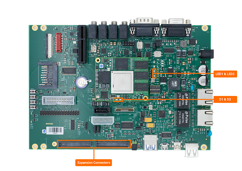
User Button via Expansion Board
This section of the guide will walk through the use of a user made Push Button populated directly onto the PHYTEC Expansion Board (PCM-957).
With the phyCORE-AM57x powered off and with the power supply removed, hook up a through-hole push button to the pin 23C and to the supply rail at pin 51C. Use the following circuit diagram for reference:
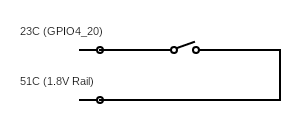
Note
GPIO4_20 is an undefined signal in the device tree and therefore will default to its reset state, which internally pulls down the pin. Thus, we need to pull the signal high when the button is pressed.
Once wired up, reconnect the power supply and boot into Linux.
Use the following command to export the GPIO signal in sysfs:
Target (Linux)echo 180 > /sys/class/gpio/export
Set GPIO4_20 as an input:
Target (Linux)echo in > /sys/class/gpio/gpio180/direction
Lets try polling the state of the GPIO4_20 signal:
Target (Linux)cat /sys/class/gpio/gpio180/value
Expected Outputroot@phycore-am57xx-1:~# cat /sys/class/gpio/gpio180/value 0
Now try polling the state of the button again while pressing and holding the push button we just wired up! You should see that the state of the signal went from 0 to a 1.
GPIO Signal Naming
The GPIO pin numbering of the phyCORE-AM57x schematic is represented differently from the device identifier used by the kernel. Therefore in GPIO hardware signal naming convention looks very different from the software GPIO naming convention. This section will walk through how to calcualte the GPIO signals and shoe how to identify which GPIO signals are in use on the developmeny kit.
Hardware to Software
Using the development kit’s carrier board and SOM schematics the hardware GPIO signal GPIO1_28 (LED1) at SOM connector A52 pin.
See which GPIO signals have been allocated by running the following command.
cat /sys/kernel/debug/gpio
root@phycore-am57xx-1:~# cat /sys/kernel/debug/gpio
gpiochip0: GPIOs 0-31, parent: platform/4ae10000.gpio, gpio-0-31:
gpio-26  (                    |home                ) in  lo IRQ
gpio-27  (                    |menu                ) in  lo IRQ
gpio-28  (                    |pcm-948:led1        ) out lo
gpio-29  (                    |pcm-948:led2        ) out lo

gpiochip1: GPIOs 32-63, parent: platform/48051000.gpio, gpio-32-63:
gpio-44  (                    |encoder@0           ) in  lo IRQ
gpio-54  (                    |vbus                ) in  hi IRQ

gpiochip2: GPIOs 64-95, parent: platform/48053000.gpio, gpio-64-95:
gpio-68  (                    |pcie-reset          ) out hi ACTIVE LOW
gpio-71  (                    |pcie-clk-oe         ) out hi

gpiochip3: GPIOs 96-127, parent: platform/48055000.gpio, gpio-96-127:

gpiochip4: GPIOs 128-159, parent: platform/48057000.gpio, gpio-128-159:

gpiochip5: GPIOs 160-191, parent: platform/48059000.gpio, gpio-160-191:
gpio-168 (                    |regulator-vtt       ) out hi
gpio-169 (                    |phycore:red         ) out lo
gpio-170 (                    |phycore:green       ) out hi

gpiochip6: GPIOs 192-223, parent: platform/4805b000.gpio, gpio-192-223:
gpio-199 (                    |id                  ) in  lo IRQ
gpio-205 (                    |wp                  ) out hi

gpiochip7: GPIOs 224-255, parent: platform/4805d000.gpio, gpio-224-255:
gpio-251 (                    |cd                  ) in  lo IRQ ACTIVE LOW
gpio-252 (                    |wp                  ) in  lo
GPIO SOC Modules |
GPIO Hardware Signal |
Section |
|---|---|---|
gpiochip0 |
GPIO1 |
0-31 |
gpiochip1 |
GPIO7 |
32-63 |
gpiochip2 |
GPIO8 |
64-95 |
gpiochip3 |
GPIO2 |
96-127 |
gpiochip4 |
GPIO3 |
128-159 |
gpiochip5 |
GPIO4 |
160-191 |
gpiochip6 |
GPIO5 |
192-223 |
gpiochip7 |
GPIO6 |
224-255 |
Looking at the section “gpiochip0”, since it translates to GPIO1, you can see the first software GPIO signal is gpio-28 for GPIO1. By adding 0 and the hardware signal(GPIO1_28) together the proper software singal name can be found.
0+28 = 28
Now you know that gpio-28 (software) is GPIO1_28 (hardware).
Software to Hardware
In order to figure out which hardware GPIO signals are already allocated simply subtract the software GPIO singal from the GPIO bank starting section.
Find the GPIO bank section by running the following command on the development kit.
Target (Linux)cat /sys/kernel/debug/gpio
The GPIO4 bank correlates gpiochip5 which starts at gpio-160. To find which hardware GPIO signal phycore:red corresponds to gpio-169, subtract gpio-169 from the start of the GPIO bank (gpio-160).
169-160 = 9
Now you know that gpio-169 (software) is GPIO4_9 (hardware).