I2C
The Inter-Integrated Circuit (I2C) interface is a two-wire, bidirectional serial bus that provides a simple and efficient method for data exchange among devices. The phyCORE-AM57x provides five independent I2C buses at the phyCORE connector directly from the processor. This guide will show you how to test the I2C interface on the phyCORE-AM57x development kit. To learn more information about the phyCORE-AM57x Inter-Integrated Circuit (I2C) interface, please see section 8.3 in the Hardware Manual.
Note
The AM57x processor supports up to 5x I2C interfaces. Only three of these are supported on the phyCORE-AM57x development kit by default but others can be enabled via pin multiplexing.
Interface |
sysfs Path |
|---|---|
I2C1 |
/dev/i2c-0 |
I2C3 |
/dev/i2c-2 |
I2C4 |
/dev/i2c-3 |
Requirements
I2C device ( Accelerometer )
Using I2C1
Power on the development kit and boot into Linux.
List the available I2C devices. There will be a few devices that appear in /dev/ and each is a different I2C interface.
List all the I2C busses in the system.
The i2c-tools package contains a heterogeneous set of I2C tools to interact with I2C slave devices from userspace. BSP images have i2c-tools packaged by default
Use the “i2cdetect” command to scan the I2C1 bus for devices. This command outputs the address of all devices on the I2C1 bus.
The I2C1 (/dev/i2c-0) interface is heavily utilized on the phyCORE-AM57x development kit. Devices onboard the SOM such as the PMIC, EEPROM and RTC are connected on this bus.
Target (Linux)i2cdetect -y -r 0Expected Outputroot@phycore-am57xx-1:~# i2cdetect -y -r 0 0 1 2 3 4 5 6 7 8 9 a b c d e f 00: -- -- -- -- -- -- -- -- -- -- -- -- -- 10: -- -- -- -- -- -- -- -- -- -- -- -- -- -- -- -- 20: -- -- -- -- -- -- -- -- -- -- -- -- -- -- -- -- 30: -- -- -- -- -- -- -- -- -- -- -- -- -- -- -- -- 40: -- -- -- -- -- -- -- -- -- -- -- -- -- -- -- -- 50: UU -- -- -- -- -- -- -- UU UU UU 5b -- -- -- -- 60: -- -- -- -- -- -- -- -- UU -- -- -- -- -- -- -- 70: -- -- -- -- -- -- -- --
Note
UU indicates that the device with that particular address is tied to a kernel driver and you will be unable to communicate with the device via i2c commands (i2cset and i2cget).
The detected interfaces should match with the devices connected to I2C1 on the development kit.
Interface |
Address (7-bit) |
|---|---|
PMIC |
0x58 0x59 0x5A 0x5B |
EEPROM |
0x50 |
RTC |
0x68 |
Interacting with I2C1
The I2C1 (/dev/i2c-0) interface is heavily utilized on the phyCORE-AM57x development kit. Devices onboard the SOM such as the PMIC, EEPROM and RTC are connected on this bus.
Use i2cdetect from Linux to scan the bus for devices:
Target (Linux)i2cdetect -y -r 0
This command outputs the address of all devices on the I2C1 bus. You should see something similar to the below:
Example Outputroot@am57xx-phycore-kit:~# i2cdetect -y -r 0 0 1 2 3 4 5 6 7 8 9 a b c d e f 00: -- -- -- -- -- -- -- -- -- -- -- -- -- 10: -- -- -- -- -- -- -- -- -- -- -- -- -- -- -- -- 20: -- -- -- -- -- -- -- -- -- -- -- -- -- -- -- -- 30: -- -- -- -- -- -- -- -- -- -- -- -- -- -- -- -- 40: -- -- -- -- -- -- -- -- -- -- -- -- -- -- -- -- 50: UU -- -- -- -- -- -- -- UU UU UU 5b -- -- -- -- 60: -- -- -- -- -- -- -- -- 68 -- -- -- -- -- -- -- 70: -- -- -- -- -- -- -- --Note
UU indicates that the address is connected to a driver. You will be unable to talk to this device via i2c commands i2cset and i2cget.
Connecting the Accelerometer
Now ‘poweroff’ the development kit and connect up the accelerometer before booting the kit back into Linux.
Target (Linux)poweroff
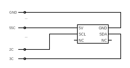
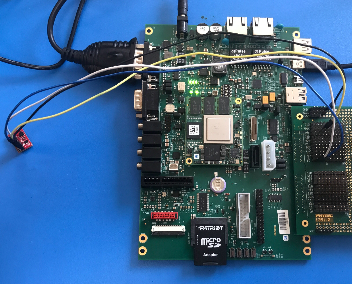
Connect the PHYTEC Expansion Board (PCM-957) to the carrier board and then connect the sensor by following the circuit diagram.
If you run the same i2cdetect command you should be able to confirm that a new device has appeared on the I2C1 bus:
Target (Linux)i2cdetect -y -r 0
Example Outputroot@am57xx-phycore-kit:~# i2cdetect -y -r 0 0 1 2 3 4 5 6 7 8 9 a b c d e f 00: -- -- -- -- -- -- -- -- -- -- -- -- -- 10: -- -- -- -- -- -- -- -- -- -- -- -- -- 1d -- -- 20: -- -- -- -- -- -- -- -- -- -- -- -- -- -- -- -- 30: -- -- -- -- -- -- -- -- -- -- -- -- -- -- -- -- 40: -- -- -- -- -- -- -- -- -- -- -- -- -- -- -- -- 50: UU -- -- -- -- -- -- -- UU UU UU 5b -- -- -- -- 60: -- -- -- -- -- -- -- -- 68 -- -- -- -- -- -- -- 70: -- -- -- -- -- -- -- --
Since the accelerometer was simply attached to the BUS without any knowledge of it having been provisioned into the Linux device tree the device address comes up as its true address 0x1d as opposed to ‘UU’. This means we can interact with it directly in userspace using the i2cget and i2cset utilities, check out the following userspace driver for bump detection!
Sensor Script
Open a text editor to write a script:
Note
The vi text editor begins in “Command Mode” and you must first hit the ‘i’ key in order to enter “Insert Mode”. Using the arrow keys to navigate, make the necessary changes and then hit ESC to go back to “Command mode”. Now enter “:wq” to write the file and quit.
Pro Tip: Use the right click on your mouse to paste! This will only work if you are in “Insert Mode” first.
vi ~/bumpDetect.sh
Enter the following and save the file:
~/bumpDetect.sh#!/bin/bash echo Input Sparkfun RedBot-Accelerometer bus: read -r bus echo Input Sparkfun RedBot-Accelerometer address: read -r addy i2cset -y "$bus" "$addy" 0x2B 0x40 #Reset the accelerometer i2cset -y "$bus" "$addy" 0x0E 0x02 #Set dynamic range to 8g from default 2g i2cset -y "$bus" "$addy" 0x2A 0x05 #Enable the device #Constantly check if there is any change in acceleration in the Z axis state=$(i2cget -y "$bus" "$addy" 0x05) while true; do temp=$(i2cget -y "$bus" "$addy" 0x05) if [ "$state" != "$temp" ]; then echo Bump! usleep 200000 state=$(i2cget -y "$bus" "$addy" 0x05) fi doneChange the permissions such that you can execute the script:
Target (Linux)chmod +x ~/bumpDetect.sh
Now run the script:
Target (Linux)~/bumpDetect.sh
When prompted, enter the bus you connected the device to (which was I2C1) and the address found earlier (the kernel representd this bus as /dev/i2c-0) Both must be given in hexidecimal form!
Example Usageroot@am57xx-phycore-kit:~# ~/bumpDetect.sh Input Sparkfun RedBot-Accelerometer bus: 0x00 Input Sparkfun RedBot-Accelerometer address: 0x1d
With the accelerometer resting on the table surface, try tapping the table surface!
The accelerometer is pretty sensitive so you should be able to tap the table anywhere, and very lightly, to get a bump to register (Note that the example is only polling the Z axis, so tapping the sides of the table will probably not register a bump).
Press Ctrl + C to quit the process.