PWM
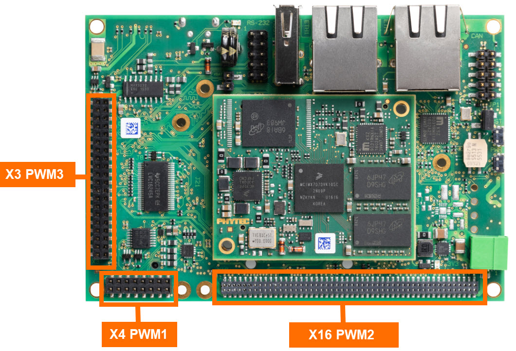
The phyCORE-i.MX7 SOM exposes four GPIO signals that can be multiplexed to output a PWM signal. The carrier board offers access to three of these four PWM signals. This guide outlines the basic steps of exporting this channel, configuring it, and enabling it to control the brightness of an LED.
PWM Signal |
Signal Name |
Connecter Header |
Pin |
|---|---|---|---|
PWM1 |
X_SAI1_MCLK |
X4 Expansion Header |
6 |
PWM2 |
X_PWM2 |
X16 Expansion Header X11: J10 = 2+3 |
30 12 |
PWM3 |
X_PWM3 |
X3 Expansion Header |
38 |
PWM4 |
X_nWDOG_RST |
U21 |
Part of Power Voltage Supervisor Circuit |
Requirements
2x M/M Jumper Wires
Bread board
LED
220 Ohm TH Resister
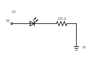
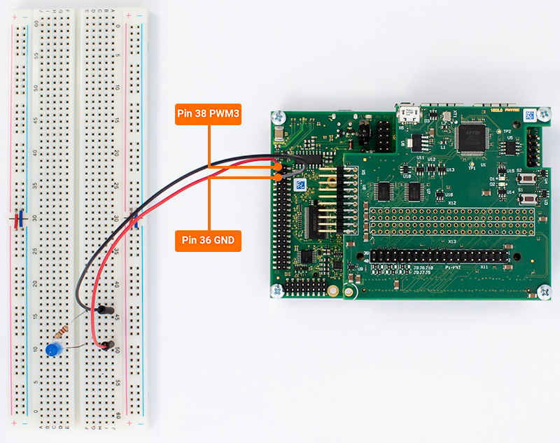
Connect an LED
Power off the kit. Connect 2x M/M jumper wires from the expansion header X3 to a breadboard. On the breadboard, arrange a 220 Ohm resistor in series with an LED.
Signal Name |
X3 Connector Pin |
Description |
|---|---|---|
X_PWM3 |
38 |
3.3V PWM Channel |
Step-by-step guide
Note
PWM3 is disabled by default for general purpose and is reserved for controlling the backlight brightness on the PEB-AV-02 Parallel Touch Display. In order to free up this PWM Channel, download this modified device tree blob (imx7d-phyboard-zeta-004-PWM.dtb) and move it to your bootable SD Card. This device tree disables support for the the PEB-AV-02 Display and frees up this PWM Channel.
See the end of this guide for more details regarding the modifications made to the device tree source.
Poweroff your phyCORE-i.MX7 development kit and remove the SD Card. Connect the SD Card to your Ubuntu Host Machine.
On your Ubuntu Host Machine:
Download the above device tree blob.
Using the Terminal, navigate to the download location:
Host (Ubuntu)cd ~/Downloads
Now transfer the device tree blob to the boot partition of the SD Card:
Host (Ubuntu)sudo cp imx7d-phyboard-zeta-004-PWM.dtb /media/user/Boot\ imx7d-/ && sync
Unmount the SD Card from your Host Machine before ejecting the card.

Now insert the SD Card back into the phyCORE-i.MX7 kit and press any key during boot to stop in U-Boot.
Enter the following commands to utilize the new device tree before booting into Linux:
Host (Ubuntu)setenv fdt_file imx7d-phyboard-zeta-004-PWM.dtb saveenv boot
To request a PWM channel from the kernel, write a 0 to the export attribute:
Target (Linux)echo 0 > /sys/class/pwm/pwmchip0/export
The duty cycle and period are set to 0 by default so we will need to configure these before enabling the PWM channel:
Target (Linux)echo 1000000 > /sys/class/pwm/pwmchip0/pwm0/period echo 100000 > /sys/class/pwm/pwmchip0/pwm0/duty_cycle
Note
The duty cycle and period attributes are expressed in nanoseconds (10-9 seconds).
For this example we are using a period of 1 ms with a duty cycle of .1 ms which is the same as saying our signal is at 1 kHz with a 10% duty cycle.
Enable the channel:
Target (Linux)echo 1 > /sys/class/pwm/pwmchip0/pwm0/enable
You should now see that the LED is very dim. To increase the brightness you must increase the duty cycle. The following command changes the duty cycle to 50%.
Target (Linux)echo 500000 > /sys/class/pwm/pwmchip0/pwm0/duty_cycle
The following command increases the duty cycle to 90%.
Target (Linux)echo 900000 > /sys/class/pwm/pwmchip0/pwm0/duty_cycle
Disabling the Channel
Target (Linux)echo 0 > /sys/class/pwm/pwmchip0/pwm0/enable
Un-exporting the Channel
Target (Linux)echo 0 > /sys/class/pwm/pwmchip0/unexport
Get Fancy!
Open a text editor to write a script:
Target (Linux)vi ~/pulseLED.sh
Enter the following and save the file:
Tip
The vi text editor begins in “Command Mode” and you must first hit the ‘i’ key in order to enter “Insert Mode”. Using the arrow keys to navigate, make the necessary changes and then hit ESC to go back to “Command mode”. Now enter “:wq” to write the file and quit.
Pro Tip: Use the right click on your mouse to paste. This will only work if you are in “Insert Mode” first.
#!/bin/bash

dc=0
max_dc=1000000
step=25000

#Re-request the PWM Channel incase its already in use
echo 0 > /sys/class/pwm/pwmchip0/unexport
echo 0 > /sys/class/pwm/pwmchip0/export

#PWM config
echo $max_dc > /sys/class/pwm/pwmchip0/pwm0/period
echo $dc > /sys/class/pwm/pwmchip0/pwm0/duty_cycle
echo 1 > /sys/class/pwm/pwmchip0/pwm0/enable


while true; do
        while (("$dc" < "$max_dc")); do
               dc=$((dc + step))
               echo $dc > /sys/class/pwm/pwmchip0/pwm0/duty_cycle
               sleep 0.025
       done
       while (("$dc" > 0)); do
               dc=$((dc - step))
               echo $dc > /sys/class/pwm/pwmchip0/pwm0/duty_cycle
               sleep 0.025
       done
done
Change the permissions in order to execute the script:
Target (Linux)chmod +x ~/pulseLED.sh
Now run the script in the back ground:
Target (Linux)~/pulseLED.sh &
Check out that pulsing LED!
To end the background process, enter the following:
Target (Linux)killall pulseLED.sh
The LED will stay on at the brightness it was at when the process was killed. To turn this off enter the following to disable and then un-export the LED.
Target (Linux)echo 0 > /sys/class/pwm/pwmchip0/pwm0/enable && echo 0 > /sys/class/pwm/pwmchip0/unexport
Note
To revert back to the original device tree:
Enabling PWM in the Device Tree
Note
This section is for advanced users hoping to learn more about customizing the Kernel. You will likely want to skip this section if you are just working through the guides to validate your hardware.
In order to enable PWM3 on your own, you will first have to build the BSP by following the :ref: BSPDev-7 guides. Once done, we can modify the device tree source and then recompile just the Kernel (this will take far less time then building the entire BSP).
After building the BSP, open the imx7d-phyboard-zeta-004.dts using the Vim Text Editor:
Host (Ubuntu)vim $YOCTO_DIR/build/tmp/work/imx7d_phyboard_zeta_004-poky-linux-gnueabi/linux-phytec-fsl/4.14.78+git_v4.14.78-phy2-r0/git/arch/arm/boot/dts/imx7d-phyboard-zeta-004.dts
Using the arrow keys to navigate, comment out the line enabling the PEB-AV-02 Parallel Display Adapter. Note that doing this will render the PEB-AV-02 Parallel Display incompatible with the phyCORE-i.MX7. The resulting file after the change is shown below (an arrow was included to show the line that needs to be changed, don’t include this arrow in the actual file).
Tip
The vi text editor begins in “Command Mode” and you must first hit the ‘i’ key in order to enter “Insert Mode”. Using the arrow keys to navigate, make the necessary changes and then hit ESC to go back to “Command mode”. Now enter “:wq” to write the file and quit.
Pro Tip: Use the right click on your mouse to paste. This will only work if you are in “Insert Mode” first.
/*
 * Copyright (C) 2019 PHYTEC America, LLC
 *
 * This program is free software; you can redistribute it and/or modify
 * it under the terms of the GNU General Public License version 2 as
 * published by the Free Software Foundation.
 *
 *
 * DTS for PHYTEC kit KPB-01910-004
 */
/dts-v1/;

#include "imx7d.dtsi"                   /* Dual Processor */
#include "imx7-phycore-som.dtsi"        /* Superset - includes all SOM population options */
#include "imx7d-pba-c-09.dtsi"          /* Carrier board */

/*
#include "imx7-peb-av-02.dtsi"           Parallel LCD adapter                                                      <---------Comment out this line as shown
*/

#include "imx7-peb-d-rpi.dtsi"          /* PEB-D-RPI module */
#include "imx7d-pcm-061-2110111c.dtsi"  /* SOM variant */
Once the file is saved and closed, recompile just the Kernel by using the following build-time optimization:
Host (Ubuntu)bitbake linux-phytec-fsl -f -c compile && bitbake linux-phytec-fsl
The changes will be reflected in the generated binary $YOCTO_DIR/build/tmp/deploy/images/imx7d-phyboard-zeta-004/imx7d-phyboard-zeta-004.dtb which can be moved to the Boot partition of your SD Card.