ADC
The versatile phyCORE-i.MX7 SOM provides four 12-bit ADC input channels (ADC_IN[0:3]) suitable for various applications. These ADC signals can be accessed through the PEB-D-RPI Expansion Board via the X13 header. This guide is designed to walk you through the process of effectively testing all four channels by connecting a bench-top power supply.

Requirements
A Philips Head Screw Driver
Soldering Equipment
Solder Iron
Flux
Solder
Vent
2x Power Supply Leads
A Power Supply
PEB-D-RPI Expansion Board (Included in kit)
1.8V Power Rail for PEB-D-RPI
Since there are no accessible 1.8V rails on the Expansion Board, a power supply or a voltage divider + potentiometer will be necessary to create a ~1.8V supply.
Soldering Pins to PEB-D-RPI
Note
After pin headers are populated, some Raspberry Pi Hats may no longer seat correctly.
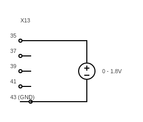
ADC_IN0 through ADC_IN3 can be accessed on the PEB-D-RPI Expansion Board of the development kit through the X13 connector at pins 35, 37, 39 and 41 respectively. However, since the ADC channels are all referenced to 1.8V it will be necessary procure or create a 1.8V supply in order to properly test these interfaces.
With the phyBOARD-Zeta powered off and with the power supply removed, remove the 2 bolts securing the PEB-D-RPI Expansion Board with a the screw driver.
Becareful when removing the PEB-D-RPI Expansion Board from the carrier board. Too much torque will bend the long connector pins. Gently rock the connector back and forth and slowly lift it up as vertically as possible.
With the PEB-D-RPI Expansion board removed, solder the 5x 2.54 mm pitch pin headers to the #35-43 pins at X13.
Signal |
Connector X13 |
|---|---|
ADC_IN0 |
35 |
ADC_IN1 |
37 |
ADC_IN2 |
39 |
ADC_IN3 |
41 |
GND |
43 |

Reassemble the phyBOARD-Zeta by re-securing the PEB-D-RPI expansion oard to the carrier board.
Kit Setup
Disconnect the bench-top power supply from the phyBOARD-Zeta. Set the voltage to a value within the range of 0V to 1.8V and establish a current limit of 200 mA.
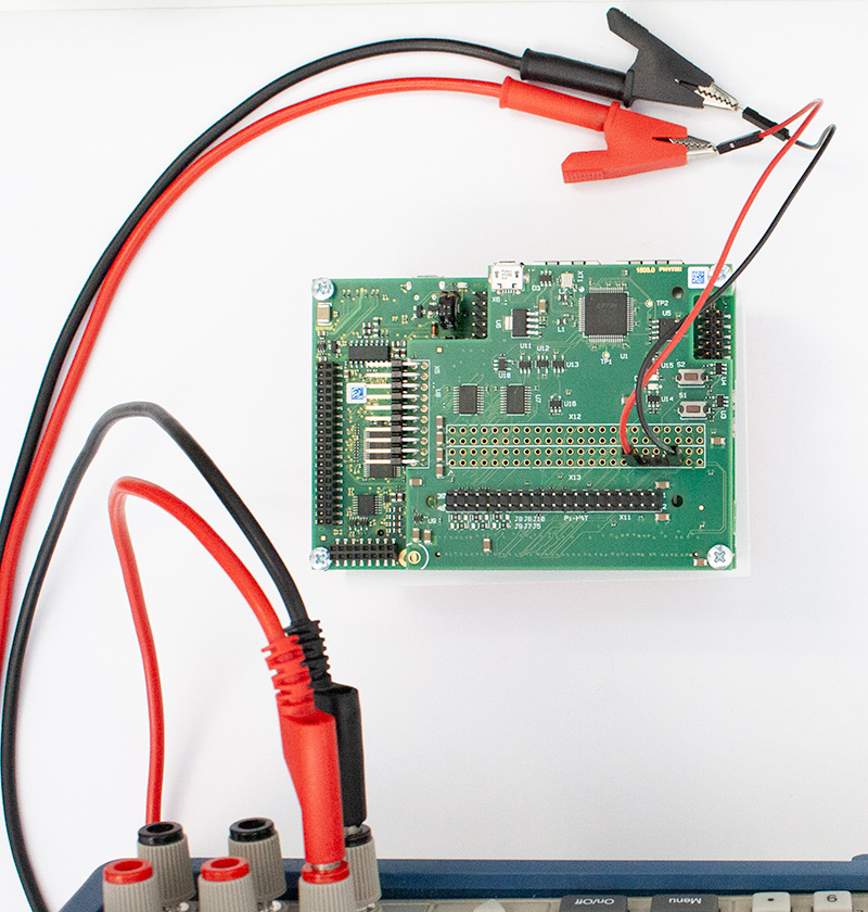
Boot the phyCORE-i.MX7 into Linux and connect the power supply to pins 35 and 43 on the PEB-D-RPI’s X13 header. See the below circuit diagram for reference.
Read the ADC
To read incoming data on ADC_IN0 (pin 35), replace “in_voltage0_raw” with the corresponding signal name of the desired channel to use a different ADC channel.
cat /sys/bus/iio/devices/iio\:device0/in_voltage0_raw
Below is the code block showing the command corresponding to reading the ADC on each channel. Comments following “#” are included for clarity but will be ignored by your Kernel:
cat /sys/bus/iio/devices/iio\:device0/in_voltage0_raw                 # To read ADC_IN0
cat /sys/bus/iio/devices/iio\:device0/in_voltage1_raw                 # To read ADC_IN1
cat /sys/bus/iio/devices/iio\:device0/in_voltage2_raw                 # To read ADC_IN2
cat /sys/bus/iio/devices/iio\:device0/in_voltage3_raw                 # To read ADC_IN3
Calculating the Voltage
The ADC registers are 12 bits, capable of reading values from 0 to 4095. Using the ADC reading, you can calculate the voltage at the pin using the following formula:

Adjust the output of the bench-top power supply (do not exceed 1.8V). Utilize the provided command to read the voltage change across the ADC channel from 0V to 1.8V.
root@phyboard-zeta-imx7d-1:~# cat /sys/bus/iio/devices/iio\:device0/in_voltage0_raw
4
root@phyboard-zeta-imx7d-1:~# cat /sys/bus/iio/devices/iio\:device0/in_voltage0_raw
926
root@phyboard-zeta-imx7d-1:~# cat /sys/bus/iio/devices/iio\:device0/in_voltage0_raw
1581
root@phyboard-zeta-imx7d-1:~# cat /sys/bus/iio/devices/iio\:device0/in_voltage0_raw
2209
root@phyboard-zeta-imx7d-1:~# cat /sys/bus/iio/devices/iio\:device0/in_voltage0_raw
3199
root@phyboard-zeta-imx7d-1:~# cat /sys/bus/iio/devices/iio\:device0/in_voltage0_raw
4094
ADC Readings |
Voltage |
|---|---|
4 |
0.002 |
2209 |
0.97 |
4094 |
1.799 |