GPIO
The phyCORE-i.MX7 SOM brings out a selection of GPIOs to the Carrier Board. Many of these signals have been made accessible on the PEB-D-RPI Expansion Board included with your development kit. This guide walks through the basic steps of toggling and reading the state of these IO interfaces.
User LED (D13)
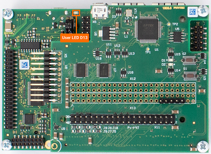
The green user-configurable LED (D13) is located on the carrier board. This LED is ON by default when the CPU is running, but we can export and toggle it for general use.
The LED (D13) is controlled by the signal X_GPIO2_10. This GPIO signal is represented in software as gpio-42. In the next section “GPIO Signal Naming” we’ll see that this GPIO signal is already allocated to name pbac09-led-1. This indicates that a driver has claimed this gpio, and this can be confirmed by checking the linux device tree. The driver is gpio-leds.
Let’s take a look at the sysfs interface that the gpio-leds driver are located in.
ls /sys/class/leds/
root@phyboard-zeta-imx7d-1:~# ls /sys/class/leds/
mmc0::@  mmc2::@  pbac09-led-1@  pebdrpi-led-1@  pebdrpi-led-2@
Turn OFF the LED.
Target (Linux)echo 0 > /sys/class/leds/pbac09-led-1/brightness
Turn ON the LED.
Target (Linux)echo 1 > /sys/class/leds/pbac09-led-1/brightness
We can also leverage the driver to do more interesting things with the LED. Let’s configure the GPIO as a Linux heartbeat for example:
echo "heartbeat" > /sys/class/leds/pbac09-led-1/trigger
The heartbeat trigger can be turned OFF like so:
echo "none" > /sys/class/leds/pbac09-led-1/trigger
PED-D-RPI Expansion Board LEDs
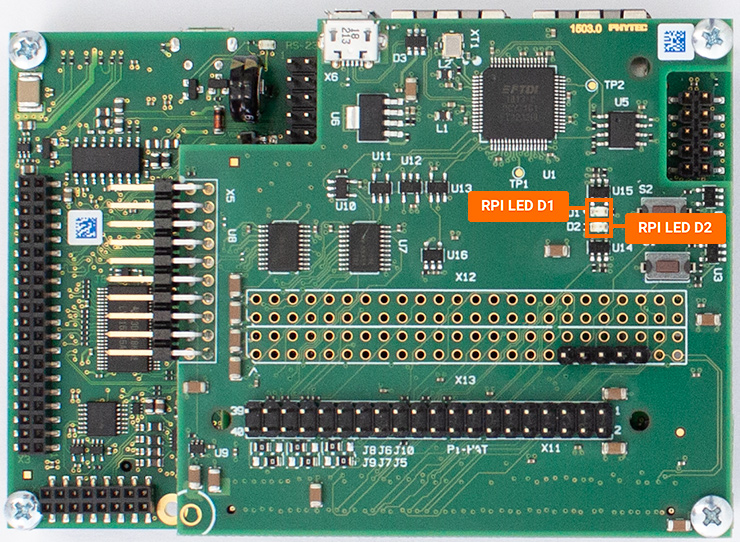
Use the following command to turn OFF D1:
Target (Linux)echo 0 > /sys/class/leds/pebdrpi-led-1/brightness
Use the following command to turn OFF D2:
Target (Linux)echo 0 > /sys/class/leds/pebdrpi-led-2/brightness
Similarly, writing a one to the LED’s brightness attribute will turn them ON:
Target (Linux)echo 0 > /sys/class/leds/pebdrpi-led-1/brightness echo 0 > /sys/class/leds/pebdrpi-led-2/brightness
Let’s configure the D2 as a Linux heartbeat for example:
echo "heartbeat" > /sys/class/leds/pebdrpi-led-2/trigger
The heartbeat trigger can be turned OFF like so:
echo "none" > /sys/class/leds/pebdrpi-led-2/trigger
PED-D-RPI Expansion Board Buttons
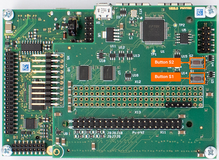
We can poll the state of the input GPIO just by reading /sys/kernel/debug/gpio
Target (Linux)cat /sys/kernel/debug/gpio | grep "button"
Expected Outputroot@phyboard-zeta-imx7d-1:~# cat /sys/kernel/debug/gpio | grep "button" gpio-41 ( |pebdrpi_button_1 ) in lo IRQ gpio-130 ( |pebdrpi_button_2 ) in lo IRQ
Now try running that command again while holding down the S1 button:
Expected Outputroot@phyboard-zeta-imx7d-1:~# cat /sys/kernel/debug/gpio | grep "button" gpio-41 ( |pebdrpi_button_1 ) in hi IRQ gpio-130 ( |pebdrpi_button_2 ) in lo IRQ
We can see that the pin goes from “lo” to “hi” when the button is pressed (note that the push button pulls the pin down… BUT the GPIO is configured as a ACTIVE_HIGH within the linux device tree which explains the seemingly reverse behavior).
Another option for viewing button presses is to leverage the gpio-keys driver and the input events that it generates:
Target (Linux)cat /dev/input/event0 | hexdump
With that above command running as an active process, try pushing the User buttons S1 and S2. You should see a large block of hexadecimal data printed to the screen for each button press.
Note
These blocks of data are input_event structures that identify the key code assigned to the GPIO (see the linux device tree), when the button press occurred, and the type of button press event that was generated (long press, single press, button release, etc). See Documentation/input/input.rst within the kernel source for more information.
Calculating GPIO Signal Names
In order to match signal names in the phyCORE-i.MX7 hardware to the device name in sysfs, use the following equation:
Hardware Signal = GPIO(Bank)_(num)
sysfs GPIO Device = (Bank -1)*32 + num
For example:
Hardware Signal = GPIO2_10
sysfs GPIO Device = (2 - 1)*32 + 10 = 42
GPIO2_10 is represented as gpio-42 in sysfs
We can confirm this with the debug gpio table.
cat /sys/kernel/debug/gpio
 root@phyboard-zeta-imx7d-1:~# cat /sys/kernel/debug/gpio
 gpiochip0: GPIOs 0-31, parent: platform/30200000.gpio, 30200000.gpio:
 gpio-5   (                    |regulator-usb-otg1-v) out hi

 gpiochip1: GPIOs 32-63, parent: platform/30210000.gpio, 30210000.gpio:
 gpio-40  (                    |pebdrpi-led-1       ) out hi
 gpio-41  (                    |pebdrpi_button_1    ) in  lo IRQ
 gpio-42  (                    |pbac09-led-1        ) out lo
 gpio-45  (                    |regulator-boot-buffe) out lo
 gpio-47  (                    |pebdrpi-led-2       ) out lo
 gpio-60  (                    |phy-reset           ) out hi
 gpio-62  (                    |phy-reset           ) out hi

 gpiochip2: GPIOs 64-95, parent: platform/30220000.gpio, 30220000.gpio:

 gpiochip3: GPIOs 96-127, parent: platform/30230000.gpio, 30230000.gpio:
 gpio-103 (                    |regulator-usb-otg2-v) out lo
 gpio-108 (                    |cts                 ) in  hi IRQ ACTIVE LOW
 gpio-109 (                    |rts                 ) out hi ACTIVE LOW

 gpiochip4: GPIOs 128-159, parent: platform/30240000.gpio, 30240000.gpio:
 gpio-128 (                    |cd                  ) in  lo IRQ ACTIVE LOW
 gpio-130 (                    |pebdrpi_button_2    ) in  lo IRQ

 gpiochip5: GPIOs 160-191, parent: platform/30250000.gpio, 30250000.gpio:

 gpiochip6: GPIOs 192-223, parent: platform/30260000.gpio, 30260000.gpio:
Signal trace X_GPIO2_10 back to the green LED D13 on the carrier board.
GPIO and gpiochip GPIO SOC Modules
GPIO Hardware Signal
Section
gpiochip0
GPIO1
0-31
gpiochip1
GPIO2
32-63
gpiochip2
GPIO3
64-95
gpiochip3
GPIO4
96-127
gpiochip4
GPIO5
128-159
gpiochip5
GPIO6
160-191
gpiochip6
GPIO7
192-223
Exporting GPIO Signals
Thus far in this guide we have gone over the control of GPIOs assigned to specific gpio-X drivers within the kernel, now let’s look into exporting and controlling unused GPIOs. For this guide we will target GPIO4_21 which is brought out to pin 7 of the X11 expansion connector.
First, convert the hardware resource GPIO4_21 into it’s software representation. We should come up with GPIO4_21 = GPIO(Bank)_(num) = (4 - 1)*32 + 21 = gpio-117 in Linux.
Export this GPIO in the kernel:
Target (Linux)echo 117 > /sys/class/gpio/export
This will create a new sysfs directory /sys/class/gpio/gpio117 (note that this step will not work for GPIOs already reserved by a driver).
Navigate into the new directory and take a look around:
Target (Linux)cd /sys/class/gpio/gpio456 ls
Similar to the features exposed by the gpio-leds driver outlined above in this guide, exporting GPIOs within sysfs creates a directory full of files that enable us to control the GPIO from userspace. We can check the current configuration of the GPIO interface by reading some of these files:
Target (Linux)cat direction cat value cat active_low
Expected Outputroot@phyboard-zeta-imx7d-1:gpio117# cat direction in root@phyboard-zeta-imx7d-1:gpio117# cat value 1 root@phyboard-zeta-imx7d-1:gpio117# cat active_low 0
Using a DMM, with the GND pointer touching the GND signal at pin 6 on X11 and the power pointer touching GPIO4_21 at pin 7 on X11, the measured voltage should be approximately 0V.
Next, configure the kernel to use this pin as a output:
Target (Linux)echo out > direction
Drive GPIO4_21 pin 7 high.
Target (Linux)echo 1 > value
Using a DMM, with the GND pointer touching the GND signal at pin 6 on X11 and the power pointer touching GPIO4_21 at pin 7 on X11, the measured voltage should be approximately 3.3V.