I2C
The Inter-Integrated Circuit (I2C) interface is a two-wire, bidirectional serial bus that provides a simple and efficient method for data exchange among devices. The phyCORE-i.MX7 SOM supports up to four independent I2C modules. This guide provides information on how to view, access, and interact with the I2C interfaces on the phyBOARD-i.MX7 development kit.
Requirements
I2C device ( Accelerometer )
PEB-D-RPI Expansion Board (Included in kit)
Viewing I2C devices
Power on the development kit and boot into Linux.
List the available I2C devices. There will be a few devices that appear in /dev/ and each is a different I2C interface.
Target (Linux)ls /dev/i2c*
You should see some device files, one of which (device /dev/i2c-0) corresponds to the I2C1 interface on the phyCORE-i.MX7.
I2C Devices Hardware Interface
Sysfs Path
I2C0
/dev/i2c-0
I2C2
/dev/i2c-1
I2C3
/dev/i2c-2
I2C4
/dev/i2c-3
Note
The I2C3 is disabled by default and it is normal to have the device i2c-2 unlisted in sysfs.
List all the I2C busses in the system.
The i2c-tools package contains a heterogeneous set of I2C tools to interact with I2C slave devices from userspace. BSP images have i2c-tools packaged by default
Target (Linux)i2cdetect -l
Expected Outputroot@phyboard-zeta-imx7d-1:~# i2cdetect -l i2c-0 i2c 30a20000.i2c I2C adapter i2c-3 i2c 30a50000.i2c I2C adapter
I2C1 Devices
The I2C1 interface is heavily utilized on the phyCORE-i.MX7 development kit. Devices onboard the SOM such as EEPROM, RTC and PMIC are all connected on this bus. In addition, I2C1 is routed out to the Expansion Board with default jumper configurations set.
Use i2cdetect from Linux to scan the bus for devices. This command outputs the address of all devices on the I2C1 bus.
Target (Linux)i2cdetect -y -r 0
Expected Output0 1 2 3 4 5 6 7 8 9 a b c d e f 00: -- -- -- -- -- UU -- -- -- -- -- -- -- 10: -- -- -- -- -- -- -- -- -- -- -- -- -- -- -- -- 20: -- -- -- -- -- -- -- -- -- -- -- -- -- -- -- -- 30: -- -- -- -- -- -- -- -- -- -- -- -- -- -- -- -- 40: -- -- -- -- -- -- -- -- -- -- -- -- -- -- -- -- 50: UU -- -- -- -- -- -- -- 58 -- -- -- -- -- -- -- 60: -- -- -- -- -- -- -- -- UU -- -- -- -- -- -- -- 70: -- -- -- -- -- -- -- --
Note
UU indicates that the device connected is tied to a driver. You will be unable to talk to this device via i2c command (i2cset and i2cget).
The EEPROM M24C32 has two different addresses (0x50 and 0x58) but one has been reserved in the device tree.
These detected interfaces match with the devices connected to I2C1 on the development kit.
I2C1 Interfaces Interface
Address
Description
PMIC
0x08
Power Management IC
EEPROM
0x50
4kB EEPROM on SOM
RTC
0x68
External RTC on SOM
Connecting the Accelerometer
This portion of the guide will walk you through the use of a I2C capable sensor.
Now ‘poweroff’ the development kit and connect up the accelerometer before booting the kit back into Linux.
Target (Linux)poweroff
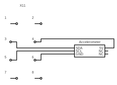
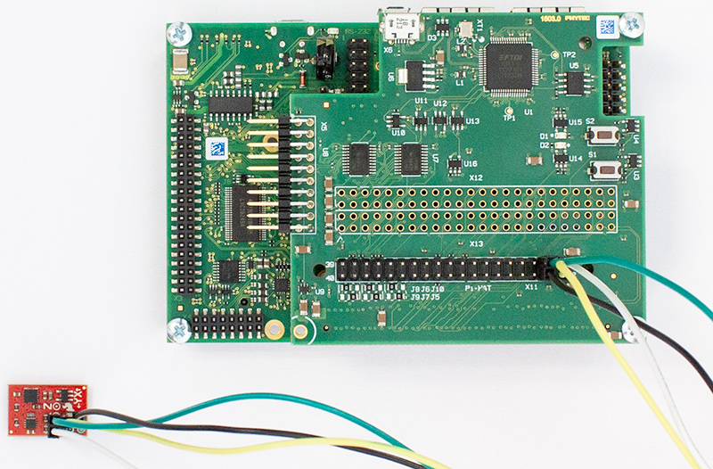
With your phyCORE-i.MX7 powered off and the power supply removed, connect the sensor to the X11 connector on the PEB-D-RPI Expansion Board by following the circuit diagram.
I2C Device Pin |
PEB-D-RPI Signal |
PEB-D-RPI Connector - Pin |
|---|---|---|
VCC |
VDD_5V0 |
X11 - Pin 4 |
GND |
GND |
X11 - Pin 6 |
SCL |
EXP_CONN_MUX7 |
X11 - Pin 5 |
SDA |
EXP_CONN_MUX8 |
X11 - Pin 3 |
Power on the phyCORE-i.MX7 and login to Linux as root.
If you run the same i2cdetect command you should be able to confirm that a new device has appeared on the I2C1 bus:
Target (Linux)i2cdetect -y -r 0
Expected Output0 1 2 3 4 5 6 7 8 9 a b c d e f 00: -- -- -- -- -- UU -- -- -- -- -- -- -- 10: -- -- -- -- -- -- -- -- -- -- -- -- -- 1d -- -- 20: -- -- -- -- -- -- -- -- -- -- -- -- -- -- -- -- 30: -- -- -- -- -- -- -- -- -- -- -- -- -- -- -- -- 40: -- -- -- -- -- -- -- -- -- -- -- -- -- -- -- -- 50: UU -- -- -- -- -- -- -- 58 -- -- -- -- -- -- -- 60: -- -- -- -- -- -- -- -- UU -- -- -- -- -- -- -- 70: -- -- -- -- -- -- -- --
Since the accelerometer was simply attached to the BUS without any knowledge of it having been provisioned into the Linux device tree the device address comes up as its true address 0x1d as opposed to ‘UU’. This means we can interact with it directly in userspace using the i2cget and i2cset utilities, check out the following userspace driver for bump detection!
Bump Detect Userspace Driver
Open a text editor to write a script:
Target (Linux)vi ~/bumpDetect.sh
Enter the following and save the file:
Note
The vi text editor begins in “Command Mode” and you must first hit the ‘i’ key in order to enter “Insert Mode”. Using the arrow keys to navigate, make the necessary changes and then hit ESC to go back to “Command mode”. Now enter “:wq” to write the file and quit.
Pro Tip: Use the right click on your mouse to paste. This will only work if you are in “Insert Mode” first.
#!/bin/bash

echo Input Sparkfun RedBot-Accelerometer bus:
read -r bus
echo Input Sparkfun RedBot-Accelerometer address:
read -r addy

i2cset -y "$bus" "$addy" 0x2B 0x40          #Reset the accelerometer
i2cset -y "$bus" "$addy" 0x0E 0x02          #Set dynamic range to 8g from default 2g
i2cset -y "$bus" "$addy" 0x2A 0x05          #Enable the device

#Constantly check if there is any change in acceleration in the Z axis
state=$(i2cget -y "$bus" "$addy" 0x05)

while true; do
       temp=$(i2cget -y "$bus" "$addy" 0x05)
       if [ "$state" != "$temp" ];
       then
              echo Bump!
              sleep 0.2
              state=$(i2cget -y "$bus" "$addy" 0x05)
      fi
done
Change the permissions in order to execute the script:
Target (Linux)chmod +x ~/bumpDetect.sh
Now run the script:
Target (Linux)~/bumpDetect.sh
When prompted, enter the bus you connected the device to (which was I2C1) and the address found earlier (the kernel representd this bus as /dev/i2c-0) Both must be given in hexidecimal form!
Expected Inputroot@phyboard-zeta-imx7d-1:~# ~/bumpDetect.sh Input Sparkfun RedBot-Accelerometer bus: 0x00 Input Sparkfun RedBot-Accelerometer address: 0x1D
With the accelerometer resting on the table surface, try tapping the table surface!
The accelerometer is pretty sensitive so you should be able to tap the table anywhere, and very lightly, to get a bump to register (Note that the example is only polling the Z axis, so tapping the sides of the table will probably not register a bump).
Expected Outputroot@phyboard-zeta-imx7d-1:~# ~/bumpDetect.sh Input Sparkfun RedBot-Accelerometer bus: 0x00 Input Sparkfun RedBot-Accelerometer address: 0x1d Bump! Bump! Bump! Bump! Bump!
Press Ctrl + C to quit the process.