Display (Parallel)
The phyCORE-i.MX7 development kit breaks out audio and video signals to the AV Connectors X3 and X4. This guide explains how to connect and use these interfaces using the PEB-AV-02 Display adapter in conjunction with a 7” EDT Display.
Note
See the end of this guide for further information regarding advanced Parallel Display configurations.
Requirements
LCD Display Adapter (PEB-AV-02)
7’’ EDT Display (AC104)
Setting up the Display
Completely turn off the phyCORE-i.MX7 development kit and disconnect the power supply.
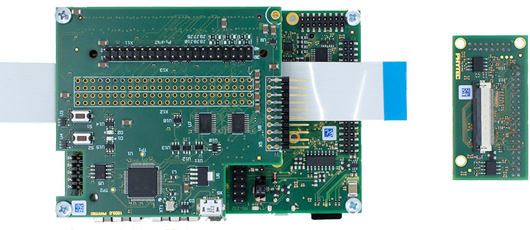
Thread the LCD ribbon cable through the middle of the kit (between the RPI Expansion Board and the Carrier Board)
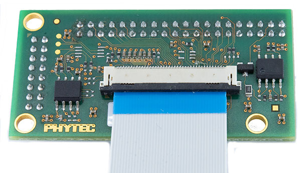
Pull out the black latch from the white sleeve to open the connector.

Insert the LCD ribbon cable into the connector on the LCD Display Adapter and secure it by pushing the black latch back into the sleeve.
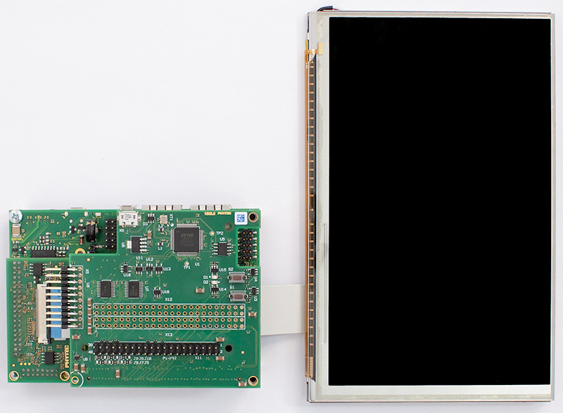
Now attach the LCD Display Adapter to the phyCORE-Zeta Carrier Board at connectors X3 and X4 as shown below:
Now reconnect the power supply and boot into Linux.
During boot up you should see Tux the Penguin appear on the screen before being presented with a simple GUI.
You may be prompted to calibrate the display for accurate touch recognition
Advanced Parallel Display Configurations
Parallel Display Jumper Configurations
Warning
Due to the small footprint of the solder jumpers, we recommend using caution when modifying these. Please contact our sales team if you require any options beyond the default configuration.
The phyBOARD-i.MX7 provides one solder jumper (J) at J2 for Parallel Display touch controller I2C address configurations.
Reference Designator |
Jumper Seeting |
Description |
|---|---|---|
J2 |
1+2 (Default) |
Sets the U9 touch controller I2C address to 0x41 |
J2 |
2+3 |
Sets the U9 touch controller I2C address to 0x44 |