PEB-D-RPI Expansion Board
The phyCORE-i.MX7 development kit features a PEB-D-RPI Expansion Board for convenient interface evaluation. This guide will explain how to use these features in supported environments. For Raspberry Pi HAT support, please see Raspberry Pi HAT.
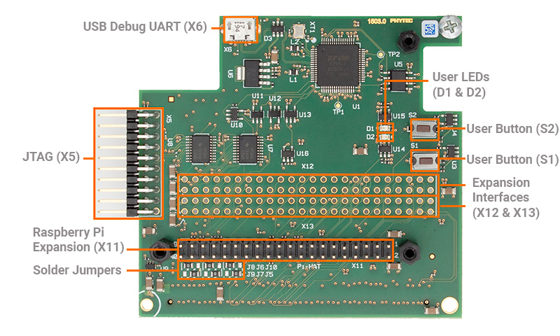
X5 JTAG 20-pin Debug Header
The phyCORE-i.MX7 SOM features a single JTAG interface located on the PEB-D-RPI Expansion Board at connector X5. Header X5 provides ARM JTAG debugger support specifically designed for the phyCORE-i.MX7. For more information about JTAG see JTAG.
X6 USB to Debug UART
The phyCORE-i.MX7 is set up to use UART1 by default for console input and output through the PEB-D-RPI Expansion Board’s X6 micro-USB connector. While this connector supports both UART1 and UART2 for serial data, only UART1 is configured in the BSP by default. UART2 is reserved for PHYTEC’s FreeRTOS software running on the M4 core.
U2 EEPROM
The PREB-D-RPD expansion board allows users to access the I2C4 interface for reading and writing data to an onboard 4KB EEPROM. The EEPROM is found under the ‘i2c4’ node in ‘imx7-peb-d-rpi.dtsi’ and accessed as a file in Linux’s sysfs.
D1 & D2 User LEDs
User LEDs D1 and D2 demonstrate how to utilize GPIO pins as outputs for device control. They are individually registered under the node ‘phytec_leds’ in the Expansion Board Linux device tree file ‘imx7-peb-d-rpi.dtsi’. Their status and control can be accessed within Linux’s sysfs directory structure.
To turn the LEDs on and off, run the following commands on the target:
Target (Linux)echo 0 > /sys/class/leds/pebdrpi-led-1/brightness #Turn D1 OFF echo 1 > /sys/class/leds/pebdrpi-led-1/brightness #Turn D1 ON echo 0 > /sys/class/leds/pebdrpi-led-2/brightness #Turn D2 OFF echo 1 > /sys/class/leds/pebdrpi-led-2/brightness #Trun D2 ON
LED Light Show!
Impress your friends or co-workers with your technical prowess!
Open a text editor to write a script:
Target (Linux)vi ~/lightShow.sh
Copy and paste the following code block into the file. .. note:: The vi text editor begins in “Command Mode” and you must first hit the ‘i’ key in order to enter “Insert Mode”. Using the arrow keys to navigate, make the necessary changes and then hit ESC to go back to “Command mode”. Now enter “:wq” to write the file and quit.
Pro Tip: Use the right click on your mouse to paste. This will only work if you are in “Insert Mode” first.
#!/bin/bash

for i in `seq 1 20`; do
    echo 0 > /sys/class/leds/pebdrpi-led-1/brightness
    echo 1 > /sys/class/leds/pebdrpi-led-2/brightness
    sleep 0.
    echo 1 > /sys/class/leds/pebdrpi-led-1/brightness
    echo 0 > /sys/class/leds/pebdrpi-led-2/brightness
    sleep 0.5
done
echo 0 > /sys/class/leds/pebdrpi-led-1/brightness
Change the permissions in order to execute the script:
Target (Linux)chmod +x ~/lightShow.sh
Now run the script in the background:
Target (Linux)~/lightShow.sh &
The light show will end automatically after approximately 20 seconds. To end it early you can enter the following command:
Target (Linux)killall lightShow.sh
X11 Exporting GPIO Signals
The 40-pin header located at X11 can be populated with a Raspberry Pi HAT or can be utilized as a standard expansion header.
Thus far in this guide we have gone over the control of GPIOs assigned to specific gpio-X drivers within the kernel, now let’s look into exporting and controlling unused GPIOs. For this guide we will target GPIO4_21 which is brought out to pin 7 of the X11 expansion connector.
First, convert the hardware resource GPIO4_21 into it’s software representation. We should come up with GPIO4_21 = GPIO(Bank)_(num) = (4 - 1)*32 + 21 = gpio-117 in Linux.
Export this GPIO in the kernel:
Target (Linux)echo 117 > /sys/class/gpio/export
This will create a new sysfs directory /sys/class/gpio/gpio117 (note that this step will not work for GPIOs already reserved by a driver).
Navigate into the new directory and take a look around:
Target (Linux)cd /sys/class/gpio/gpio456 ls
Similar to the features exposed by the gpio-leds driver outlined above in this guide, exporting GPIOs within sysfs creates a directory full of files that enable us to control the GPIO from userspace. We can check the current configuration of the GPIO interface by reading some of these files:
Target (Linux)cat direction cat value cat active_low
Expected Outputroot@phyboard-zeta-imx7d-1:gpio117# cat direction in root@phyboard-zeta-imx7d-1:gpio117# cat value 1 root@phyboard-zeta-imx7d-1:gpio117# cat active_low 0
Using a DMM, with the GND pointer touching the GND signal at pin 6 on X11 and the power pointer touching GPIO4_21 at pin 7 on X11, the measured voltage should be approximately 0V.
Next, configure the kernel to use this pin as a output:
Target (Linux)echo out > direction
Drive GPIO4_21 pin 7 high.
Target (Linux)echo 1 > value
Using a DMM, with the GND pointer touching the GND signal at pin 6 on X11 and the power pointer touching GPIO4_21 at pin 7 on X11, the measured voltage should be approximately 3.3V.
X11 Raspberry Pi Hat
Header X11 offers Raspberry Pi HAT hardware support and a convenient connection point for GPIO or other interface signals routed to the Expansion Board. For Raspberry Pi HAT support information, please refer to the Raspberry Pi HAT documentation.
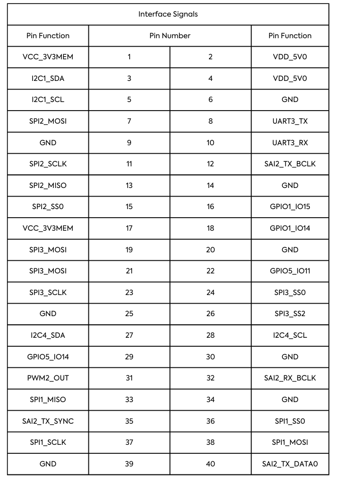
X11 Interface Signals Map
The tables below display the GPIO bank, pins, and Raspberry Pi-compatible interface signals mapped to the 40-pin header on the PEB-D-RPI Expansion Board.

X11 Jumpers
The 40-pin header also employs soldered jumpers to toggle the selection of specific Raspberry Pi-compatible interface signals to certain pins, facilitating support for various Raspberry Pi HATs. The following table outlines the pins and signals controlled by the jumpers:
Jumper |
Pin |
Default Signal (Position 1+2) |
Alternative Signal (Position 2+3) |
|---|---|---|---|
J5 |
31 |
PWM2_OUT |
SAI2_TX_BCLK |
J6 |
33 |
SPI1_MISO |
SAI2_TX_SYNC |
J7 |
35 |
SD2_DATA2 |
SPI1_MISO |
J8 |
37 |
SPI1_SCLK |
SAI2_TX_DATA0 |
J9 |
40 |
SD2_DATA3 |
SPI1_SCLK |
J10 |
12 |
SD2_DATA1 |
PWM2_OUT |
J11 |
29 |
GPIO5_IO14 |
SPI1_MOSI |
J12 |
38 |
SPI1_MOSI |
GPIO5_IO14 |
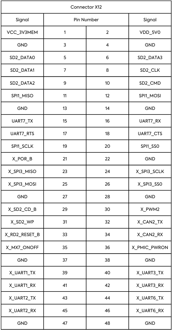
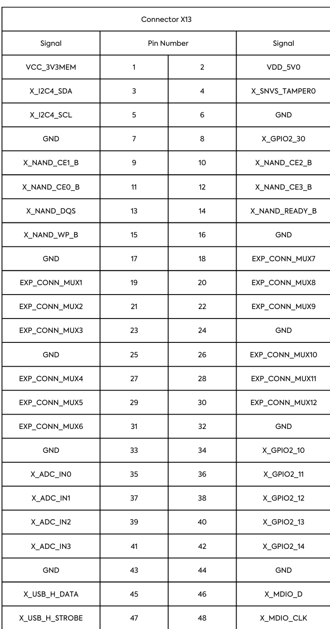
X12 & X13 Expansion Interface Headers
The unpopulated headers X12 and X13 allow access to Expansion Board signals not exposed to the Raspberry Pi-compatible 40-pin header. The tables below display the signals brought out to the unpopulated headers:
Advanced Signal Configurations
The expansion connector X16 on the phyBOARD-i.MX7 Carrier Board provides a way to implement custom expansion boards for extended functionality and development. Standard interfaces such as UART, SPI, I2C, and various GPIO are available at the expansion connector and therefore are accessible on the PEB-D-RPI Expansion Board on the phyCORE-i.MX7 development kit.
Warning
Due to the small footprint of the solder jumpers, we recommend using caution when modifying these. Please contact our sales team if you require any options beyond the default configuration.
There are 12 jumpers on the phyBOARD-i.MX7 development kit that are comprised of four solder pads, which provide the option of routing the RGMII2 signals out to the expansion connector rather than to the phyBOARD-i.MX7 Carrier Board’s Ethernet PHY.
Jumper |
Position |
Signal Setting |
|---|---|---|
J9 |
1+2 (Default) 3+4 (Default) 2+3 |
X_RGMII2_RXD0 is routed to the ETH2 phy.X_SNVS_TAMPER1 is routed to the expansion connector at EXP_CONN_MUX1. X_RGMII2_RXD0 is routed to the expansion connector at EXP_CONN_MUX1. X_SNVS_TAMPER1 is not connected to the expansion connector. |
J10 |
1+2 (Default) 3+4 (Default) 2+3 |
X_RGMII2_RXD1 is routed to the ETH2 phy.X_SNVS_TAMPER2 is routed to the expansion connector at EXP_CONN_MUX2. X_RGMII2_RXD1 is routed to the expansion connector at EXP_CONN_MUX2. X_SNVS_TAMPER2 is not connected to the expansion connector. |
J11 |
1+2 (Default) 3+4 (Default) 2+3 |
X_RGMII2_RXD2 is routed to the ETH2 phy. X_SD1_RESET_B is routed to the expansion connector at EXP_CONN_MUX3. X_RGMII2_RXD2 is routed to the expansion connector at EXP_CONN_MUX3. X_SD1_RESET_B is not connected to the expansion connector. |
J12 |
1+2 (Default) 3+4 (Default) 2+3 |
X_RGMII2_RXD3 is routed to the ETH2 phy. X_GPIO1_O9 is routed to the expansion connector at EXP_CONN_MUX4. X_RGMII2_RXD3 is routed to the expansion connector at EXP_CONN_MUX4. X_GPIO1_09 is not connected to the expansion connector. |
J13 |
1+2 (Default) 3+4 (Default) 2+3 |
X_RGMII2_RX_CTL is routed to the ETH2 phy. X_GPIO2_15 is routed to the expansion connector at EXP_CONN_MUX5. X_RGMII2_RX_CTL is routed to the expansion connector at EXP_CONN_MUX5. X_GPIO2_15 is not connected to the expansion connector. |
J14 |
1+2 (Default) 3+4 (Default) 2+3 |
X_RGMII2_RXC is routed to the ETH2 phy. X_LCD1_RESET is routed to the expansion connector at EXP_CONN_MUX6. X_RGMII2_RXC is routed to the expansion connector at EXP_CONN_MUX6. X_LCD1_RESET is not connected to the expansion connector. |
J15 |
1+2 (Default) 3+4 (Default) 2+3 |
X_RGMII2_TXD0 is routed to the ETH2 phy. X_X_I2C1_SCL is routed to the expansion connector at EXP_CONN_MUX7. X_RGMII2_TXD0 is routed to the expansion connector at EXP_CONN_MUX7. X_I2C1_SCL is not connected to the expansion connector. |
J16 |
1+2 (Default) 3+4 (Default) 2+3 |
X_RGMII2_TXD1 is routed to the ETH2 phy. X_I2C1_SDA is routed to the expansion connector at EXP_CONN_MUX8. X_RGMII2_TXD1 is routed to the expansion connector at EXP_CONN_MUX8. X_I2C1_SDA is not connected to the expansion connector. |
J17 |
1+2 (Default) 3+4 (Default) 2+3 |
X_RGMII2_TXD2 is routed to the ETH2 phy. X_RGMII1_RX_CTL is routed to the expansion connector at EXP_CONN_MUX9. X_RGMII2_TXD2 is routed to the expansion connector at EXP_CONN_MUX9. X_RGMII1_RX_CTL is not connected to the expansion connector. |
J18 |
1+2 (Default) 3+4 (Default) 2+3 |
X_RGMII2_TXD3 is routed to the ETH2 phy. X_RGMII1_RXC is routed to the expansion connector at EXP_CONN_MUX10. X_RGMII2_RXD3 is routed to the expansion connector at EXP_CONN_MUX10. X_RGMII1_RXC is not connected to the expansion connector. |
J19 |
1+2 (Default) 3+4 (Default) 2+3 |
X_RGMII2_TX_CTL is routed to the ETH2 phy. X_RGMII1_TX_CTL is routed to the expansion connector at EXP_CONN_MUX11. X_RGMII2_TX_CTL is routed to the expansion connector at EXP_CONN_MUX11. X_RGMII1_TX_CTL is not connected to the expansion connector. |
J20 |
1+2 (Default) 3+4 (Default) 2+3 |
X_RGMII2_TXC is routed to the ETH2 phy. X_RGMII1_TXC is routed to the expansion connector at EXP_CONN_MUX12. X_RGMII2_TXC is routed to the expansion connector at EXP_CONN_MUX12. X_RGMII1_TXC is not connected to the expansion connector. |
Note
RGMII requirements should be considered when interfacing with RGMII2 via the expansion connector. It is recommended to verify all of the necessary timing budget parameters, such as trace length matching and skew/delay between clock and data, will meet the RGMII timing specifications.