USB
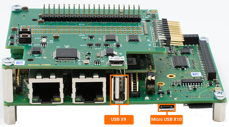
The Universal Serial Bus (USB) can serve various functions on the development kit, including external media support. The phyCORE-i.MX7 development kit offers two USB 2.0 Host and OTG capable ports through a USB A connector (X9) and a micro-USB port (X10), respectively. This guide will demonstrate how to utilize the USB Host capabilities featured on the phyCORE-i.MX7 development kit.

Requirements
Verifying USB Interface
Plug the USB drive into X9.
If the kit is powered on, the USB should be automatically detected and the Linux console will display a message similar to the one below.
Expected Outputroot@phyboard-zeta-imx7d-1:~# [ 1074.805564] usb 1-1: new high-speed USB device number 2 using ci_hdrc [ 1075.008267] usb 1-1: New USB device found, idVendor=090c, idProduct=1000, bcdDevice=11.00 [ 1075.016511] usb 1-1: New USB device strings: Mfr=1, Product=2, SerialNumber=3 [ 1075.023677] usb 1-1: Product: USB Flash Disk [ 1075.029597] usb 1-1: Manufacturer: General [ 1075.033709] usb 1-1: SerialNumber: 04NO3BEZ826XRN7H [ 1075.044723] usb-storage 1-1:1.0: USB Mass Storage device detected [ 1075.055141] usb-storage 1-1:1.0: Quirks match for vid 090c pid 1000: 400 [ 1075.064051] scsi host0: usb-storage 1-1:1.0 [ 1076.355371] scsi 0:0:0:0: Direct-Access General USB Flash Disk 1100 PQ: 0 ANSI: 4 [ 1076.369429] sd 0:0:0:0: [sda] 31506432 512-byte logical blocks: (16.1 GB/15.0 GiB) [ 1076.380545] sd 0:0:0:0: [sda] Write Protect is off [ 1076.386029] sd 0:0:0:0: [sda] No Caching mode page found [ 1076.391361] sd 0:0:0:0: [sda] Assuming drive cache: write through [ 1076.403036] sda: [ 1076.407898] sd 0:0:0:0: [sda] Attached SCSI removable disk
To list more information about the USB device and buses on the development kit use the following command.
This command will output a good chunk of information. This guide will only show a snippet of the expected output for the USB drive that was just connected.
Target (Linux)lsusb -v -s 001:002
Note
“001” refers to bus 001 and “002” refers to the device number, both of these can be found in the lsusb command.
Bus 001 Device 002: ID 090c:1000 General USB Flash Disk
Device Descriptor:
  bLength                18
  bDescriptorType         1
  bcdUSB               2.00
  bDeviceClass            0
  bDeviceSubClass         0
  bDeviceProtocol         0
  bMaxPacketSize0        64
  idVendor           0x090c
  idProduct          0x1000
  bcdDevice           11.00
  iManufacturer           1 General
  iProduct                2 USB Flash Disk
  iSerial                 3 04NO3BEZ826XRN7H
  bNumConfigurations      1
The speed of the USB device can be determined with either the lsusb -v from above or by reading the device’s “speed”
Target (Linux)cat /sys/bus/usb/devices/1-1/speed
Expected Outputroot@phyboard-zeta-imx7d-1:~# cat /sys/bus/usb/devices/1-1/speed 480
Note
USB2.0 has transmission speeds up to 480Mbit/s, also known as “full speed”.
X9 Mounting USB Stroage Devices
Verify that a device directory was established for the USB drive.
Target (Linux)ls /dev/sd*
Expected Outputroot@phyboard-zeta-imx7d-1:~# ls /dev/sd* /dev/sda
Make a directory for mounting the USB device.
Target (Linux)mkdir ~/usb_sda
Format file type.
Target (Linux)mkfs.vfat /dev/sda
Mount the USB device to the directory.
Target (Linux)mount /dev/sda ~/usb_sda/
See what media is on the USB drive.
Target (Linux)ls ~/usb_sda/
Write to the USB Host Device
Generate a random 10 MB file to test transferring data from the storage device.
Target (Linux)dd if=/dev/urandom of=test.file count=10 bs=1M
Copy the file to your storage device.
cp test.file ~/usb_sda/ && sync
Read from the USB Host Device
Copy the test file we previously created during the write process back to the host:
Target (Linux)cp ~/usb_sda/test.file readback-usb.file && sync
We can double check that the file was successfully copied to and from the USB device by checking the md5sum of the file:
Target (Linux)md5sum test.file readback-usb.file
Expected Output7397e7d412f16e3432f352e61fa876ef test.file 7397e7d412f16e3432f352e61fa876ef readback-usb.file
Unmounting HOST USB Drive
Warning
Make sure the drive is unmounted prior to physically disconnecting the device. Failure to do so may result in loss of data and corruption of files
umount ~/usb_sda/
umount /dev/sda
Advanced USB-OTG Configurations
USB-OTG Jumper Configurations
Warning
Due to the small footprint of the solder jumpers, we recommend using caution when making modifications. Please contact our sales team if you require any options beyond the default configuration.
The phyCORE-i.MX7 provides two solder jumper (J) at J5 and J6 for configuring USB-OTG signal termination.
Jumpers |
Positions |
Signal Settings |
|---|---|---|
J5 |
1+2 (Default) 2+3 |
Routes X_USB_OTG2_DN to the Micro-AB USB connector Routes X_USB_OTG2_DN to the Mini PCIe connector |
J6 |
1+2 (Default) 2+3 |
Routes X_USB_OTG2_DP to the Micro-AB USB connector Routes X_USB_OTG2_DP to the Mini PCIe connector |