Raspberry Pi HAT
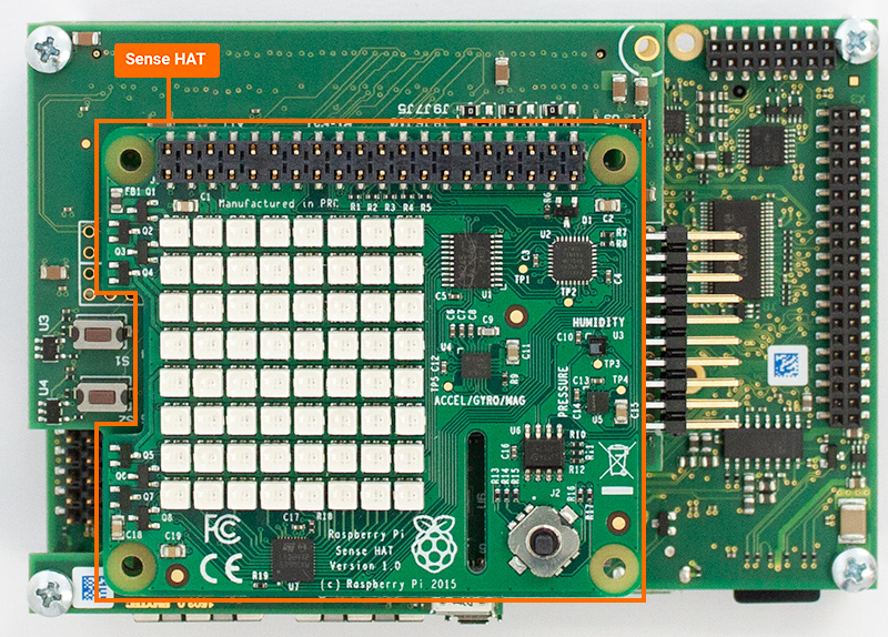
PHYTEC’s phyCORE-i.MX7 PEB-D-RPI expansion board features a 40-pin header (X11) for emulating Raspberry Pi functionality, including support for Raspberry Pi HATs. This guide demonstrates connecting and running demos with a Raspberry Pi HAT: Sense Hat on the phyCORE-i.MX7.
Requirements
Connecting Hat to PEB-D-RPI
Power off and remove power from phyCORE-i.MX7.
Note
Do not connect or disconnect a Raspberry Pi HAT to or from the PEB-D-RPI Expansion Board while the kit is powered on, as this could result in damaged products.
Connect the Sense HAT to the PEB-D-RPI expansion board via the 40-pin header (X11). The Sense hat through hole expansion header connecter can be placed directly on top of the X11 connecter.

Verify Connection
Restore power to the kit and log into Linux
Verify that the development kit has detected the Sense HAT and that the correct pin muxing and device tree overlay have been loaded by searching the bootlog.
Target (Linux)dmesg | grep phytec-hat
You should see output similar to the following lines. This output indicates that the Sense HAT was detected and the correct pin muxing and device tree overlay was loaded:
Expected Outputphytec-hat 3-0050: HAT Vendor: Raspberry Pi phytec-hat 3-0050: HAT Product: Sense HAT phytec-hat 3-0050: overlay loaded: imx7-peb-d-sense.dtb
Demos for the Sense HAT have already been included in the BSP. You can find the demos for the Sense HAT in the ‘/usr/share/phytec-rpihat-examples/sense-hat’ directory.
To run a demo that showcases the LED matrix and framebuffer functionality of the Sense HAT, run the following commands:
Target (Linux)cd /usr/share/phytec-rpihat-examples/sense-hat python rainbow.py
You should now see a slow-moving rainbow shift across the LED matrix on the Sense HAT. There are many other Python demos to try for the Sense HAT in the same directory. You can run any of them in the same manner as above by executing ‘python <script_name.py>’ on the target.
Enabling Additional GPIOs to 40-pin Header
By default, the GPIOs that are muxed to the 40-pin header on the PEB-D-RPI Expansion Board are those that only have GPIO functionality. This facilitates the use of device tree overlays that may have pin mux conflicts with additional GPIOs. To enable additional GPIOs, you must modify the device tree file ‘imx7-peb-d-rpi.dtsi’ as follows:
Under the &i2c4 entry in ‘imx7-peb-d-rpi.dtsi’, you will find a node called ‘rpi_hat_eeprom’. This node contains the pin control definitions that are loaded on boot and when the ‘phytec-hat’ driver detects a supported HAT.
The pin control entry pinctrl-0, or “default”, points to the ‘pinctrl_pebdrpi’ pin control group.
You can add an arbitrary set of pin control groups to the pin control pinctrl-0 entry which will then be loaded on boot. For example, if you wanted to enable GPIOs on the pins normally used by the UART3 interface, you would change the pin control entry pinctrl-0 to the following:
Host (imx7-peb-d-rpi.dtsi)pinctrl-0 = <&pinctrl_pebdrpi &pinctrl_uart3_gpio>;
This table contains the names of the pin control groups to add to the pin control entry pinctrl-0 if you need the use of GPIOs on specific pins:
Pin Control Group Name |
40-pin Header Pin Number |
|---|---|
pinctrl_pebdrpi |
7, 11, 12, 13, 15, 16, 18, 22, 29, 32, 35, 40 |
pinctrl_sai2_gpio |
19, 21, 23, 24 |
pinctrl_ecspi1_gpio |
33, 36, 37, 38 |
pinctrl_ecspi3_ss2_gpio |
26 |
pinctrl_uart3_gpio |
8, 10 |
pinctrl_pwm2_gpio |
31 |
The following table contains the alternative pin control group and pin number pairing if you de-solder and re-solder these jumpers in their alternative position: J5, J6, J7, J8, J9, J10, J11, and J12.
Alternative (Jumpered) Table
Pin Control Group Name |
40-pin Header Pin Number |
|---|---|
pinctrl_pebdrpi |
7, 11, 13, 15, 16, 18, 22, 29, 31, 32, 33, 37 |
pinctrl_sai2_gpio |
19, 21, 23, 24 |
pinctrl_ecspi1_gpio |
35, 36, 38, 40 |
pinctrl_ecspi3_ss2_gpio |
26 |
pinctrl_uart3_gpio |
8, 10 |
pinctrl_pwm2_gpio |
12 |