SPI
The i.MX7 processor can support up to 4x SPI interfaces. In the phyCORE-i.MX7 SOM design, up to 2x of these SPI interfaces are made available at the connectors. This guide will provide information on how to view, access and interact with the SPI3 interface on the Linux development kit.
Note
It is important to note that none of the SPI interfaces are enabled by default in the standard device tree (See the Release Notes for more information). In order to follow this guide, you will have to download and copy this custom device tree blob to the Boot partition of your bootable SD Card (Note that this device tree disables support for Raspberry Pi HATs) :
imx7d-phyboard-zeta-004-spi.dtb
You will also need this pre-compiled application for testing:
For more information on how to make the necessary device tree changes yourself, see :ref: bspSPI3-7.
Step-By-Step Guide
Download the imx7d-phyboard-zeta-004-spi.dtb device tree blob and copy it to the Boot partition of your bootable SD Card:
Host (Ubuntu)cd <download-directory> cp imx7d-phyboard-zeta-004-spi.dtb /media/user/Boot\ imx7d-/ && sync
Download the pre-compiled spidev_test application and copy it to the rootfs partition of your bootable SD Card:
Host (Ubuntu)cp spidev_test /media/user/<rootfs>/home/root/ && sync
Safely eject your bootable SD Card and insert the SD Card into your phyCORE-i.MX7 Development Kit.
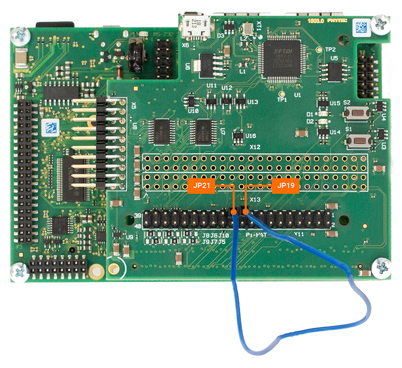
Before powering on the kit, connect a single F-F jumper cable to pins 19 and 21 on the Raspberry Pi header (connector X13) on the PED-D-RPI Expansion Board as shown:

Power on the kit and be prepared to stop in U-Boot by pressing any key when prompted.
Enter the following to configure U-Boot to load the custom device tree blob enabling SPI:
Target (U-Boot)setenv fdt_file imx7d-phyboard-zeta-004-spi.dtb saveenv boot
Once in Linux, enter the following command to load the SPI driver:
Target (Linux)modprobe spidev
We can also check and make sure the kernel module was loaded properly:
Target (Linux)lsmod
Expected Outputroot@imx7d-phyboard-zeta-004:~# lsmod Module Size Used by spidev 16384 0 iwlmvm 245760 0 iwlwifi 192512 1 iwlmvm
We should now also see a SPI device appear in the /dev directory (this will only appear after the spidev driver has been loaded):
Target (Linux)ls /dev/spi*
Expected Outputroot@imx7d-phyboard-zeta-004:~# ls /dev/spi* /dev/spidev2.0
We can see here that SPI3 in hardware corresponds to SPI2 in software. The 2.0 signifies that we are using chip select 0.
Now that SPI3 is enabled and the driver is loaded, we can launch the test application with the following command:
Target (Linux)~/spidev_test -v
Expected Outputroot@imx7d-phyboard-zeta-004:~# ~/spidev_test -v spi mode: 0x0 bits per word: 8 max speed: 500000 Hz (500 KHz) TX | 00 01 02 03 04 05 06 07 08 09 0A 0B 0C 0D 0E 0F 10 11 12 13 14 15 16 17 18 19 1A 1B 1C 1D 1E 1F |................................| RX | 00 01 02 03 04 05 06 07 08 09 0A 0B 0C 0D 0E 0F 10 11 12 13 14 15 16 17 18 19 1A 1B 1C 1D 1E 1F |................................|
Note
If SPI communication is not functioning properly, only “00”s will be printed in the “rx data”. This can be demonstrated by running the previous command again with the wire removed.
Revert to the Default Software Configuration
This guide required the use of a custom device tree blob which disabled support for Raspberry Pi HATs. Refer to this section of this guide to revert back to the default device tree configuration: