Camera
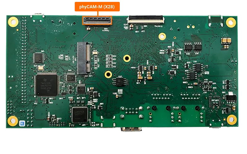
The Camera Serial Interface (CSI) is a specification of the Mobile Industry Processor Interface (MIPI) Alliance. It defines an interface between a camera and a host processor. The phyBOARD-Lyra AM62x has one CSI camera connection on the back of the carrier board, at X28. This guide will show you how to connect and take pictures with a MIPI CSI-2 camera module (VM-016 phyCAM-M). To learn more information about the phyBOARD-Lyra AM62x CSI/Camera interface, please see section 8 & 8.3 in the Hardware Manual.
Requirements
Setting Up the Camera
With the board powered off, connect the phyCAM-M module to the camera connector X28 on the carrier board.
Open the X28 connector by pulling the black tab backwards toward the center of the carrier board.
Insert the ribbon cable into the connector, with the blue tape facing outward.
Once the ribbon cable has been seated into the connector, pull the black tab back towards it’s closed position. You should hear a small click when the connector has completely closed.
Power on the development kit and stop in U-boot. Load the device tree overlay required for the parallel camera interface and then boot the board.
sh-uboot=> setenv overlays k3-am62-phyboard-lyra-vm016-mipi.dtbo
sh-uboot=> boot
Once in Linux, setup the camera pipelines.
sh-phyboard-lyra-am62xx-3:~# media-ctl -d /dev/media0 -V "'ar0144 1-0010':0 [fmt:SGRBG8_1X8/1280x800 (0,4)/1280x800 field:none colorspace:default xfer:default ycbcr:default quantization:default]"
sh-phyboard-lyra-am62xx-3:~# media-ctl -d /dev/media0 -V "'ar0144 1-0010':0 [fmt:SGRBG8_1X8/1280x800 field:none colorspace:default xfer:default ycbcr:default quantization:default]"
sh-phyboard-lyra-am62xx-3:~# media-ctl -d /dev/media0 -V "'30102000.ticsi2rx':0 [fmt:SGRBG8_1X8/1280x800 field:none colorspace:default xfer:default ycbcr:default quantization:default]"
Note
“media-ctl” configures the camera pipeline by defining the format, resolution, and other settings for the image capture.
“ar0144” refers to the CMOS digital image sensor with the pixel array of 1280H x 800V being used to capture images.
“1-0010” refers to the I2C device being used. In this case I2C1 device is being utilized.
“30102000.ticsi2rx” refers to the TI CSI interface.
Taking a Picture
To capture a PNG picture named “smile.png”, use the following gstreamer pipeline command.
sh-phyboard-lyra-am62xx-3:~# gst-launch-1.0 v4l2src num-buffers=5 device=/dev/video0 ! video/x-bayer,format=grbg,depth=8,width=1280,height=800 ! bayer2rgb ! videoconvert ! pngenc ! multifilesink location=smile.png
Setting pipeline to PAUSED ...
Pipeline is live and does not need PREROLL ...
Setting pipeline to PLAYING ...
New clock: GstSystemClock
Redistribute latency...
Got EOS from element "pipeline0".
Execution ended after 0:00:02.443544000
Setting pipeline to NULL ...
Freeing pipeline ...
Viewing Picture on HDMI
After capturing an image, you can display it on an HDMI monitor connected to the board. The following command uses GStreamer to display the PNG image:
sh-phyboard-lyra-am62xx-3:~# gst-launch-1.0 -v filesrc location=./smile.png ! pngdec ! imagefreeze ! kmssink driver-name="tidss"
The pipeline reads the PNG file, decodes it, freezes the image (since it’s a still image), and displays it on the HDMI output. The image will be shown until you press Ctrl+C to stop the GStreamer pipeline.
See Displaying Images for more details about HDMI display configuration and additional display options.