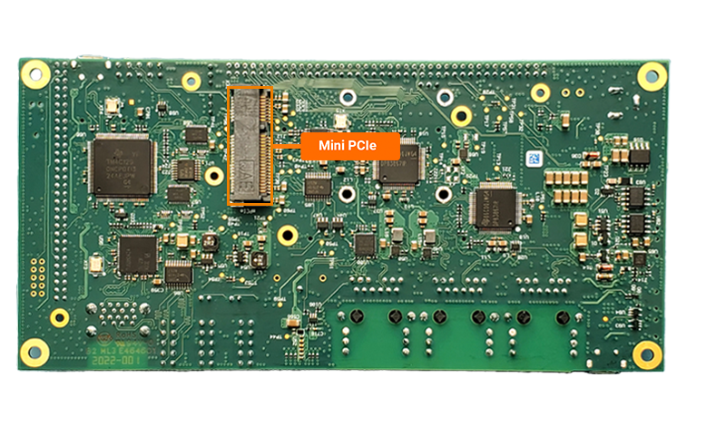
miniPCIe
The PCI Express (PCIe) interface of the phyCORE-AM64x SOM provides PCIe Gen. 2.0 (1-lane) functionality. Furthermore, the interface is backwards compatible to the Gen1 specification. This guide will show you how to do a basic functional test of the miniPCIe interface on the phyCORE-AM64x development kit. To learn more information about the phyCORE-AM64x PCIe interface, please see section 7.5 in the Hardware Manual.
Warning
The USB super speed signals are muxed between the miniPCIe interface and the USB HUB. Enabling miniPCIe (done via device tree overlay) will disable USB3.0 speeds at the stacked type-A USB connector but USB2.0 speeds will still be available.
Requirements
Development Kit Setup
First, ‘poweroff’ the development kit.
Target (Linux)poweroff
With the power removed, insert the miniPCIe adapter into the development kit’s miniPCIe slot.
It is recommended to use some hardware to secure the miniPCIe card to the development kit carrier board. A small M2 bolt and nut should do the trick.
Power on the development kit and stop in U-Boot when prompted.
Enable the miniPCIe device tree overlay (this overlay will enable the miniPCIe slot, but at the same time disable the USB HUB’s superspeed support).
setenv overlays k3-am64-phyboard-electra-pcie-usb2.dtbo
boot
Note
For more information about overlays see chapter Configuring the Bootloader.
Confirming Mini PCIe Connection
Once booted into Linux, confirm that the PCIe card was detected.
lspci
root@phyboard-electra-am64xx-2:~# lspci
00:00.0 PCI bridge: Texas Instruments Device b010
01:00.0 Ethernet controller: Intel Corporation 82574L Gigabit Network Connection
Confirm that there is a new network interface called enp1s0:
ip address
root@phyboard-electra-am64xx-2:~# ip address
1: lo: <LOOPBACK,UP,LOWER_UP> mtu 65536 qdisc noqueue state UNKNOWN group default qlen 1000
link/loopback 00:00:00:00:00:00 brd 00:00:00:00:00:00
inet 127.0.0.1/8 scope host lo
  valid_lft forever preferred_lft forever
inet6 ::1/128 scope host
  valid_lft forever preferred_lft forever
2: eth0: <NO-CARRIER,BROADCAST,MULTICAST,UP> mtu 1500 qdisc mq state DOWN group default qlen 1000
  link/ether ac:1f:0f:84:02:fc brd ff:ff:ff:ff:ff:ff
3: can0: <NOARP,UP,LOWER_UP,ECHO> mtu 16 qdisc pfifo_fast state UP group default qlen 10
  link/can
4: can1: <NOARP,UP,LOWER_UP,ECHO> mtu 16 qdisc pfifo_fast state UP group default qlen 10
  link/can
5: eth1: <NO-CARRIER,BROADCAST,MULTICAST,UP> mtu 1500 qdisc mq state DOWN group default qlen 1000
  link/ether 1a:c6:45:51:c7:58 brd ff:ff:ff:ff:ff:ff
6: eth2: <NO-CARRIER,BROADCAST,MULTICAST,UP> mtu 1500 qdisc mq state DOWN group default qlen 1000
  link/ether ca:74:6c:8d:53:d6 brd ff:ff:ff:ff:ff:ff
7. enp1s0: <NO-CARRIER,BROADCAST,MULTICAST,UP> mtu 1500 qdisc mq state DOWN group default qlen 1000
  link/ether ac:1f:0f:84:22:ff brd ff:ff:ff:ff:ff:ff
If you connect the miniPCIe adapter to a DHCP enabled Local Area Network, you should find that you are automatically assigned a valid IP address:
root@phyboard-electra-am64xx-2:~# ip address
1: lo: <LOOPBACK,UP,LOWER_UP> mtu 65536 qdisc noqueue state UNKNOWN group default qlen 1000
link/loopback 00:00:00:00:00:00 brd 00:00:00:00:00:00
inet 127.0.0.1/8 scope host lo
  valid_lft forever preferred_lft forever
inet6 ::1/128 scope host
  valid_lft forever preferred_lft forever
2: eth0: <NO-CARRIER,BROADCAST,MULTICAST,UP> mtu 1500 qdisc mq state DOWN group default qlen 1000
  link/ether ac:1f:0f:84:02:fc brd ff:ff:ff:ff:ff:ff
3: can0: <NOARP,UP,LOWER_UP,ECHO> mtu 16 qdisc pfifo_fast state UP group default qlen 10
  link/can
4: can1: <NOARP,UP,LOWER_UP,ECHO> mtu 16 qdisc pfifo_fast state UP group default qlen 10
  link/can
5: eth1: <NO-CARRIER,BROADCAST,MULTICAST,UP> mtu 1500 qdisc mq state DOWN group default qlen 1000
  link/ether 1a:c6:45:51:c7:58 brd ff:ff:ff:ff:ff:ff
6: eth2: <NO-CARRIER,BROADCAST,MULTICAST,UP> mtu 1500 qdisc mq state DOWN group default qlen 1000
  link/ether ca:74:6c:8d:53:d6 brd ff:ff:ff:ff:ff:ff
7. enp1s0: <NO-CARRIER,BROADCAST,MULTICAST,UP> mtu 1500 qdisc mq state UP group default qlen 1000
  link/ether ac:1f:0f:84:22:ff brd ff:ff:ff:ff:ff:ff
  inet 102.0.0.22/24 brd 102.0.0.224 scope global enp1s0
    valid_lft forever preferred_lft forever
The IPv4 address assigned to the development kit in the above example output is 102.0.0.22 .
To test your network connection, ping a known host:
ping google.com
Disable the Device Tree Overlay
Once done evaluating miniPCIe (maybe you want USB superspeed capability back), do the following to disable the device tree overlay we enabled at the beginning of this guide:
Reboot the board:
reboot
Once prompted, stop in U-Boot.
Issue the following U-Boot commands to restore the boot environment back to its factory settings:
env default -f -a
saveenv
boot