SPI
The Serial Peripheral Interface (SPI) is a transmit/receive, master/slave synchronous serial bus. The phyCORE-AM64x SOM provides access to seven SPI ports at the phyCORE-Connector. This guide will show you how to test the SPI interface on the phyCORE-AM64x development kit via a loopback test. To learn more information about the phyCORE-AM64x SPI, please see section 7.6 in the Hardware Manual.
Requirements
-
Note
The expansion header was designed for 2mm pins. It is acceptable to use 2.54mm jumper pins during the development and verification of interfaces. The only issue arises when you switch back to plugging in a 2mm male header for an expansion board you created.
SDHC SD card, at least 8GB for PHYTEC’s TISDK release image (Included in development kit)
Linux Host PC or Virtual Machine (Ubuntu recommended)
SD card reader (operational under Linux)
Development Kit Setup
Note
There are 2x SPI interfaces on the phyCORE-AM64x SOM but only one is set up for use on the development kit carrier board (SPI1).
In the software, the SPI1 interface can be accessed through /dev/spidev1.0
Power off and remove the power supply from the development kit.
Target (Linux)poweroff
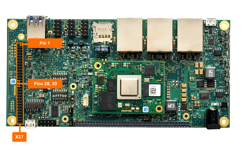
Connect pin 28 and pin 30 on the X27 expansion connector using a M-M jumper wire. These pins correspond to SPI1’s MISO and MOSI signals.
Enabling Overlay & Script
Power on the board and press any key to stop autoboot and enter U-Boot.
Type the following commands to enable the device tree overlay:
Target (U-Boot)setenv overlays k3-am64-phyboard-electra-x27-uart3-spi1.dtbo boot
Loop-back Test
Initiate a loop-back test on the SPI1 interface (/dev/spidev1.0).
Target (Linux)spidev_test -v -D /dev/spidev1.0
Expected Outputspi mode: 0x0 bits per word: 8 max speed: 500000 Hz (500 KHz) TX | FF FF FF FF FF FF 40 00 00 00 00 95 FF FF FF FF FF FF FF FF FF FF FF FF FF FF FF FF FF FF F0 0D |......@.........................| RX | FF FF FF FF FF FF 40 00 00 00 00 95 FF FF FF FF FF FF FF FF FF FF FF FF FF FF FF FF FF FF F0 0D |......@.........................|
Note
If SPI communication is not functioning properly, only “00”s or “FF”s will be printed in the “RX” line.
This can be demonstrated by running the previous command again with the jumper removed.