UART
he phyCORE-AM64x SOM provides access to up to eleven UART interfaces that can be used for configuration and data exchange with external peripheral devices. The phyCORE-AM64x development kit provides nine UART modules that can be used for configuration and data exchange with external peripheral devices.
By default, the phyCORE-AM64x development kit is configured to use UART0 (ttyS2 in the device tree) for a Linux console input and output. The UART0 singal is availble through a micro-USB connector (X20) via a FTDI chip (U95). PHYTEC recommends allocating UART0 for console access on custom designs. UART1 is also available at a 2x5 connector X4 (ttyS3) and UART3 is available at a 60 pin expansion header X27. This guide will walk through the steps needed to verify the functionality of UART1 and UART3. To learn more information about the phyCORE-AM64x UART interface, please see sections 7.7 and 10.3 in the Hardware Manual.
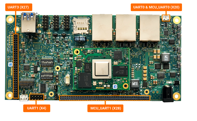
The UART channels correspond to the following connectors and system paths.
UART |
Connector |
sysfs Path |
|---|---|---|
MCU_UART0 |
X20 (Micro USB) |
ttyS0 |
MCU_UART1 |
X28 (Expansion Header) |
ttyS1 |
UART0 |
X20 (Micro USB) |
ttyS2 |
UART1 |
X4 (10-pin Header) |
ttyS3 |
UART3 |
X27 (Expansion Header) |
ttyS5 |
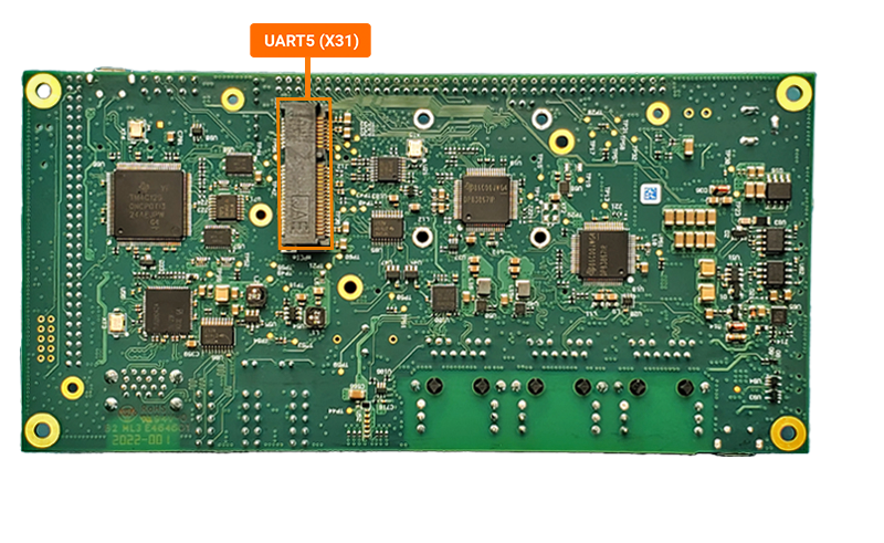
UART5 |
X31 (mPCIe) |
ttyS7 |
Requirements
USB to RS-232 Serial Adapter working with UART0
DB9 Male 2x5 to RS232 Female Cable (Included in development kit) working with UART0
USB to TTL Cable 3 pin working with UART3
3x M/M Jumper Wire working with UART3
Note
The expansion header was designed for 2mm pins. It is acceptable to use 2.54mm jumper pins during the development and verification of interfaces. The only issue arises when you switch back to plugging in a 2mm male header for an expansion board you created.
UART1 Hardware Setup
Power off and remove the power supply from the development kit.
Target (Linux)poweroff
Connect the DB9 Male 2x5 to RS232 Female Cable to the X4 connector (red line indicates Pin 1)

Connect the USB to RS-232 serial adpater to the female end of the the DB9 cable. Do not connect the cable to your Host system yet.
Power the development kit back on.
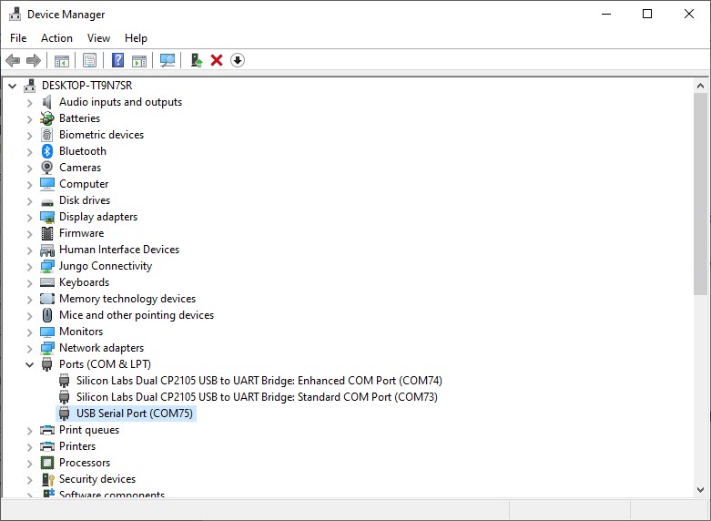
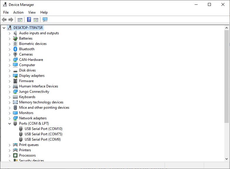
Open your Host system’s Device Manager and expand Ports (COM & LPT).
Note that there should be two COM ports named “Silcon Labs Dual CP2105 USB to UART Bridge,” these relate to X20.
Note
Windows systems can press the Windows key, type “device manager” and press ENTER.
Connect the USB to RS-232 serial adapter to your Host machine.
Take note of any new device names that appear under “Ports”. You’ll need the COM port device number in the next steps.
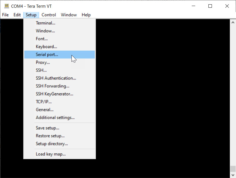
UART1 Terminal Setup
Open a new terminal window. This guide will be using TeraTerm but other emulators like PuTTY will work as well.
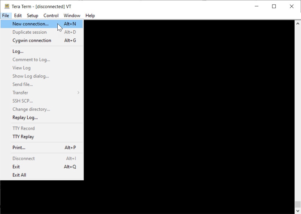
Set the serial parameters: 115200 Baud, 8 bit data, no parity bits, 1 stop bit and no flow control.

Select a COM port that coresponds to the one USB to RS-232 serial adapter port.
UART1 Setting the Baud Rate
In the terminal window connected to X20, the development kit default serial port, enter the following to set the communication rate for UART1:
Target (Linux)stty -F /dev/ttyS3 115200
Sending a Message to UART1
Now try sending a message to UART1 terminal (X4). In the X20 terminal, enter the following command:
Target (Linux)echo You did it! > /dev/ttyS3
Take a look at the UART1 terminal.
Expected Output (UART1 console)You did it!
Note
If you have trouble receiving or sending messages to a Console Terminal, ensure that you have the correct COM port set and the terminal is configured for 8 bit data, no parity bits, 1 stop bit, and a baud rate of 115200.
Receiving a Message from UART1
To receive messages from your host machine, set your Linux console to output any incoming data from the UART1 connection:
Target (Linux)cat /dev/ttyS3
Now send a message from the UART1 console to the Linux console. Type anything you want and then hit the “Enter” button.
Enter Ctrl + C in the Linux console to stop waiting for incoming data.
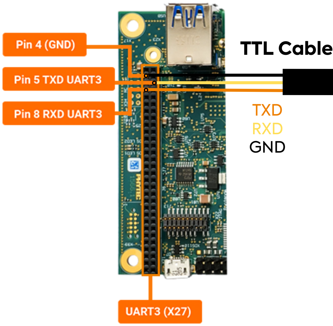
UART3 Hardware Setup
Power off and remove the power supply from the development kit.
Target (Linux)poweroff
Connect the TTL Cable to the expansion header X27. Do not connect the cable to your host system yet.
GND |
Black Connecter |
Pin 4 (X27) |
|---|---|---|
TXD |
Orange Connecter |
Pin 5 (X27) |
RXD |
Yellow Connecter |
Pin 8 (X27) |
Power the development kit back on and stop in U-Boot.
Load the device tree overlay required for UART3 and then boot the board.
Target (U-Boot)setenv overlays k3-am64-phyboard-electra-x27-uart3-spi1.dtbo boot
Note
For more information about overlays see Configuring the Bootloader.
Open your host system’s Device Manager and expand Ports (COM & LPT).
Note
Windows systems can press the Windows key, type “device manager” and press ENTER.
Connect the USB end of the TTL cable to the Host machine.
Take note of any new device names that appear under “Ports”. You’ll need the COM port device number in the next steps.
UART3 Terminal Setup
Open a new terminal window. This guide will be using TeraTerm but other emulators like PuTTY will work as well.

Set the serial parameters: 115200 Baud, 8 bit data, no parity bits, 1 stop bit and no flow control.

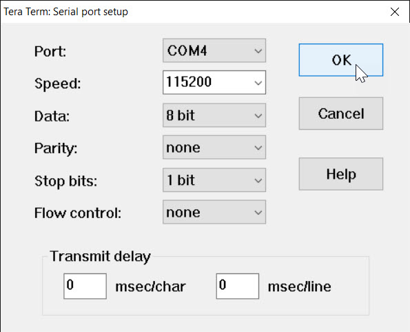
Select a COM port that corresponds to the TTL cable.
UART3 Setting the Baud Rate
In the terminal window connected to X20, the development kit default serial port, enter the following to set the communication rate for UART3:
Target (Linux)stty -F /dev/ttyS5 115200
Sending a Message to UART3
Now try sending a message to UART3 terminal. In the debug console terminal, enter the following command:
Target (Linux)echo You did it! > /dev/ttyS5
Take a look at the UART3 terminal.
Expected Output (UART3 Console)You did it!
Note
If you have trouble receiving or sending messages to a console terminal, ensure that you have the correct COM port set and the terminal is configured for 8 bit data, no parity bits, 1 stop bit, and a baud rate of 115200.
You can ensure the COM port settings in the debug console with the following command:
To set the settings to match that of the debug console use the following command:
Target (Linux)stty -F /dev/ttyS5 115200 stty -brkint ixoff -imaxbel iutf8 -iexten < /dev/ttyS5
Receiving a Message from UART3
To read messages from UART3, set your debug console to output any incoming data from the UART3 connection:
Target (Linux)cat /dev/ttyS5
Now send a message from the UART3 console to the debug console. Type anything you want and then hit the “Enter” button.
Expected Outputroot@phyboard-electra-am64xx-2:~# cat /dev/ttyS5 Hello World
Enter Ctrl + C in the Linux console to stop waiting for incoming data.