UART
The phyCORE-AM64x provides access to up to 11 UART interfaces that can be used for configuration and data exchange with external peripheral devices. The phyBOARD-Electra AM64x provides access to five of these interfaces through expansion connectors.
By default, the phyBOARD-Electra AM64x is configured to use UART0 for a Linux console input and output. The UART0 signal is available through a micro-USB connector X20 via a UART to USB bridge. PHYTEC recommends allocating UART0 for console access on custom designs. You can see all available UART interfaces in the images and tables below. To learn more information about the phyCORE-AM64x UART interface, please see sections 7.7 and 10.3 in the Hardware Manual.
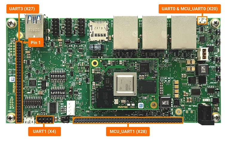
The UART channels correspond to the following connectors and system paths.
UART |
Connector |
sysfs Path |
|---|---|---|
MCU_UART0 |
X20 (Micro USB) |
ttyS0 |
MCU_UART1 |
X28 (Expansion Header) |
ttyS1 |
UART0 |
X20 (Micro USB) |
ttyS2 |
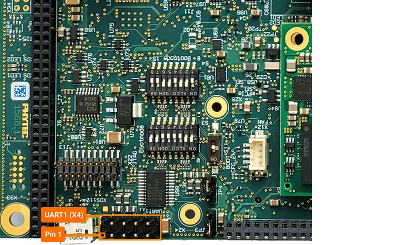
UART1 |
X4 (10-pin Header) |
ttyS3 |
UART3 |
X27 (Expansion Header) |
ttyS5 |
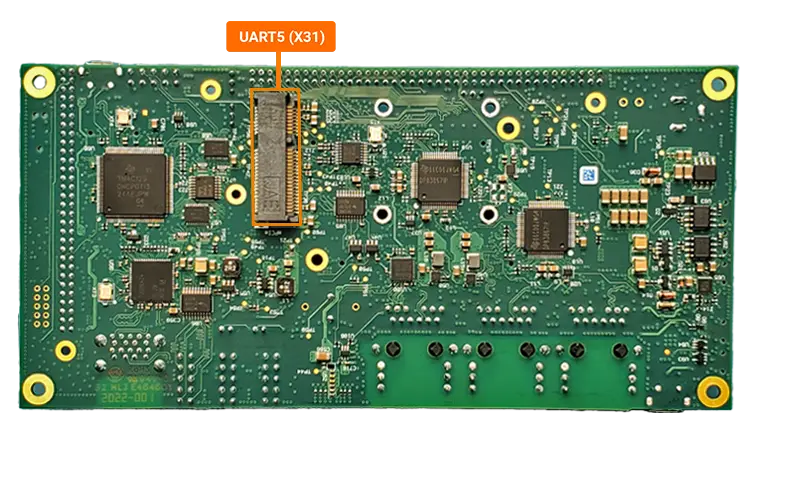
UART5 |
X31 (mPCIe) |
ttyS7 |
Requirements
Hardware Setup
Power off and remove the power supply from the phyBOARD-Electra AM64x.
sh-phyboard-electra-am64xx-2:~# poweroff
Connect the DB9 Male 2x5 to RS232 Female Cable (Included in the development kit) to the X4 connector (red line indicates Pin 1)
Connect the USB to RS-232 serial adpater to the female end of the the DB9 cable. Do not connect the cable to your Host system yet.
Power the phyBOARD-Electra AM64x back on.
Inspect dmesg output to figure out the TTL device of the UART to USB bridge cable. If you already have connected a cable to the USB debug port, your TTL device will be very likely /dev/ttyUSB3.
Setting the Baud Rate
Before using the UART interface, you need to configure the baud rate. The following command sets the baud rate to 115200 bps for the UART interface:
sh-phyboard-electra-am64xx-2:~# stty -F /dev/ttyS3 115200
You can verify the current settings using:
sh-phyboard-electra-am64xx-2:~# stty -F /dev/ttyS3 -a
Sending Messages
To send data through the UART interface, you can use the echo command to write to the device:
sh-phyboard-electra-am64xx-2:~# echo "Hello World" > /dev/ttyS3
For continuous transmission, you can use a loop:
sh-phyboard-electra-am64xx-2:~# while true; do echo "Test Message" > /dev/ttyS3; sleep 1; done
Receiving Messages
To read incoming data from the UART interface, use the cat command:
sh-host:~$ cat /dev/ttyS3
This will display any incoming messages in real-time. Press Ctrl+C to stop reading.
For debugging purposes, you can also use minicom. Install it using:
sh-host:~$ sudo apt update
sh-host:~$ sudo apt install minicom
Start minicom:
sh-host:~$ minicom -D /dev/ttyS3 -b 115200
Booting via UART
See chapter UART on how to boot from UART.