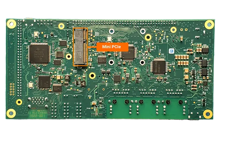
miniPCIe
The PCI Express (PCIe) interface of the phyCORE-AM64x SOM provides PCIe Gen. 2.0 (1-lane) functionality. Furthermore, the interface is backwards compatible to the Gen1 specification. This guide will show you how to do a basic functional test of the miniPCIe interface on the phyBOARD-Electra AM64x kit. To learn more information about the phyCORE-AM64x PCIe interface, please see section 7.5 in the Hardware Manual.
Warning
The USB super speed signals are muxed between the miniPCIe interface and the USB HUB. Enabling miniPCIe will disable USB3.0 speeds at the stacked type-A USB connector but USB2.0 speeds will still be available.
Requirements
Mini PCI Express Single Port RJ45 Ethernet 10/100/1000Mbps Gigabit LAN Card
Development Kit Setup
First, ‘poweroff’ the development kit.
sh-phyboard-electra-am64xx-2:~# poweroffWith the power removed, insert the miniPCIe adapter into the development kit’s miniPCIe slot.
It is recommended to use some hardware to secure the miniPCIe card to the development kit carrier board. A small M2 bolt and nut should do the trick.
Power on the development kit and stop in U-Boot when prompted.
Enable the miniPCIe device tree overlay (this overlay will enable the miniPCIe slot, but at the same time disable the USB HUB’s superspeed support).
sh-uboot:~# setenv overlays k3-am642-phyboard-electra-pcie-usb2.dtbo
sh-uboot:~# boot
Note
For more information about overlays see chapter Configuring the Bootloader.
Confirming Mini PCIe Connection
Once the system has booted into Linux, verify that the PCIe card has been detected by running:
sh-phyboard-electra-am64xx-2:~# lspci
00:00.0 PCI bridge: Texas Instruments Device b010
01:00.0 Ethernet controller: Intel Corporation I210 Gigabit Network Connection (rev 03)
This output confirms the presence of TI’s PCI bridge and the detected PCIe card. For more details about a specific device, specify the slot using the
-soption:
sh-phyboard-electra-am64xx-2:~# lspci -s 01:00.0 -vm
Device: 01:00.0
Class:  Ethernet controller
Vendor: Intel Corporation
Device: I210 Gigabit Network Connection
Rev:    03
ProgIf: 00
Since this particular PCIe card is an Ethernet controller, an additional Ethernet interface should be available. Verify this using:
sh-phyboard-electra-am64xx-2:~# ip link
1: lo: <LOOPBACK,UP,LOWER_UP> mtu 65536 qdisc noqueue state UNKNOWN mode DEFAULT group default qlen 1000
    link/loopback 00:00:00:00:00:00 brd 00:00:00:00:00:00
2: eth0: <BROADCAST,MULTICAST,UP,LOWER_UP> mtu 1500 qdisc mq state UP mode DEFAULT group default qlen 1000
    link/ether 00:b0:d0:63:c2:26 brd ff:ff:ff:ff:ff:ff
3: main_mcan1: <NOARP,UP,LOWER_UP,ECHO> mtu 16 qdisc pfifo_fast state UP mode DEFAULT group default qlen 10
    link/can
4: main_mcan0: <NOARP,UP,LOWER_UP,ECHO> mtu 16 qdisc pfifo_fast state UP mode DEFAULT group default qlen 10
    link/can
5: eth1: <BROADCAST,MULTICAST,UP,LOWER_UP> mtu 1500 qdisc mq state UP mode DEFAULT group default qlen 1000
    link/ether 00:a0:c9:00:00:00 brd ff:ff:ff:ff:ff:ff
6: eth2: <BROADCAST,MULTICAST,UP,LOWER_UP> mtu 1500 qdisc mq state UP mode DEFAULT group default qlen 1000
    link/ether 00:b0:d0:63:c2:27 brd ff:ff:ff:ff:ff:ff
7: eth3: <BROADCAST,MULTICAST,UP,LOWER_UP> mtu 1500 qdisc mq state UP mode DEFAULT group default qlen 1000
    link/ether 02:2a:c2:40:c1:4c brd ff:ff:ff:ff:ff:ff
For details on configuring and using Ethernet interfaces, refer to the Ethernet section.