UART
The i.MX RT1170 processor includes twelve LPUART controllers, several of which are exposed on the phyCORE-RT1170 module and phyBOARD-Atlas RT1170 carrier board for application use. LPUART can be evaluted directly from the Zephyr shell using the built-in uart commands, without writing any application code.
For detailed hardware-level information, refer to the 7.6 UART in the Hardware Manual.
Requirements
DB9 Male to RS232 Female Cable
DB9 to USB Cable
Jumper Cables
Hardware Setup
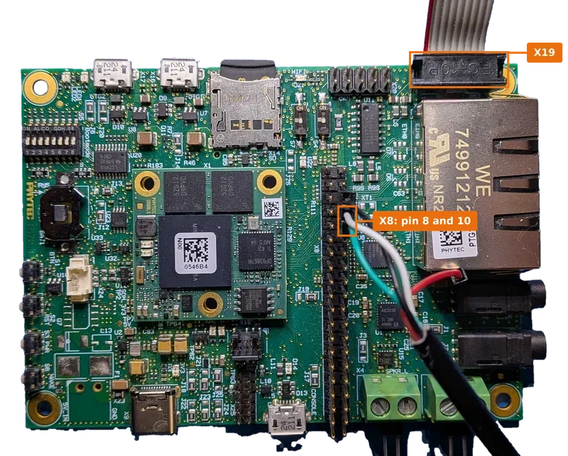
The examples below exercise uart@4008c000 (LPUART5), which is routed to connector X8 on the phyBOARD-Atlas RT1170 carrier board. Connect a UART adapter to pin 8 and pin 10 of X8 to send and receive data with this device.
Another available example is uart@40098000 (LPUART8), which is routed to the RS-232 connector X19 on the phyBOARD-Atlas RT1170 carrier board. Connect an RS-232 cable to X19 to send and receive data with this device.
Note
RS-232 (LPUART8) is functional, but hardware flow control is currently not supported.
Shell Usage
Run uart without arguments to list the available subcommands:
uart:~$ uart
uart - UART commands
Subcommands:
  write     : Write data to the UART device
              Usage: write <device> <data>
  read      : Read data from the UART device
              Usage: read <device> <duration in secs>
  config    : Get the UART device configuration
              Usage: config <device>
  baudrate  : Configure the UART device baudrate
              Usage: baudrate <device> <baudrate>
  fc        : Configure the UART device flow control
              Usage: fc <device> <none|rtscts|dtrdsr|rs485>
Checking a Device’s Configuration
Pass a UART device’s devicetree node name to config to read back its current baud rate, data bits, parity, stop bits, and flow control setting:
uart:~$ uart config uart@4008c000
Device: uart@4008c000
    Baud rate: 115200 bps
    Data bits: 8
    Parity: none
    Stop bits: 1
    Flow control: none
Writing Data
To send data out a UART device:
uart:~$ uart write uart@4008c000 abc
Connect a USB-to-UART adapter to X8 pin 8 and pin 10 as described above, and open a terminal on the corresponding host serial device to confirm the data arrives:
tio /dev/ttyUSB2
[11:21:50.630] tio v2.7
[11:21:50.630] Press ctrl-t q to quit
[11:21:50.631] Connected
abc
Reading Data
To capture data received on a UART device over a given duration (in seconds), type into the host terminal opened above while the command is running:
uart:~$ uart read uart@4008c000 10
uart:~$ uart read uart@4008c000 10
UART: Read for 10 seconds from uart@4008c000.
1234
Note
Loop back a device’s TX and RX pins, or connect it to another serial peer, to see write and read exchange data between two UART devices.
Changing Baud Rate and Flow Control
To reconfigure a device’s baud rate at runtime:
uart:~$ uart baudrate <device> <baudrate>
To change a device’s flow control mode:
uart:~$ uart fc <device> <none|rtscts|dtrdsr|rs485>
Note
For any technical questions, feel free to reach out to PHYTEC’s Support Portal!