UART
Note
The UART1 interface is only available on BSP image PD23.2.0 and later.
The phyCORE-AM62Ax SOM provides access to up to ten UART interfaces that can be used for configuration and data exchange with external peripheral devices. The phyBOARD-AM62Ax dev kit provides access to five of these interfaces through expansion connectors.
By default, the phyCORE-AM62Ax development kit is configured to use UART0 (ttyS2 in the device tree) for a Linux console input and output. The UART0 signal is available through a micro-USB connector (X49) via a FTDI chip (U90). PHYTEC recommends allocating UART0 for console access on custom designs. UART1 is also available at the expansion connector X17 (ttyS3). This guide will walk through the steps needed to verify the functionality of UART1. To learn more information about the phyCORE-AM62x UART interface, please see sections 7.5 and 11.3 in the Hardware Manual.
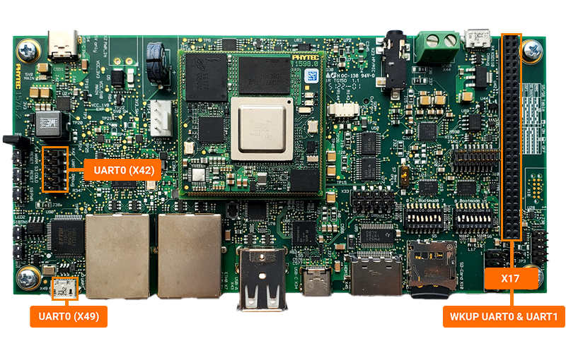
The UART channels correspond to the following connectors and system paths.
UART |
Connector |
Character Device File |
Status |
|---|---|---|---|
UART0 |
X49 (Micro USB), X42 (10-pin Header) |
/dev/ttyS2 |
Default Linux Console at X49 X42 is currently unavailable |
UART1 |
X17 (Exp Connector) |
/dev/ttyS3 |
Used for TI System Firmware Debugging |
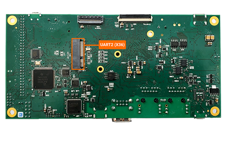
UART2 |
X36 (WiFi/BT connector) |
/dev/ttyS4 |
Not Implemented. Allocated to BT. |
Requirements
-
Note
The expansion header was designed for 2mm pins. It is acceptable to use 2.54mm jumper pins during the development and verification of interfaces. The only issue arises when you switch back to plugging in a 2mm male header for an expansion board you created.
Hardware Setup
Power off and remove the power supply from the development kit.
Target (Linux)poweroff
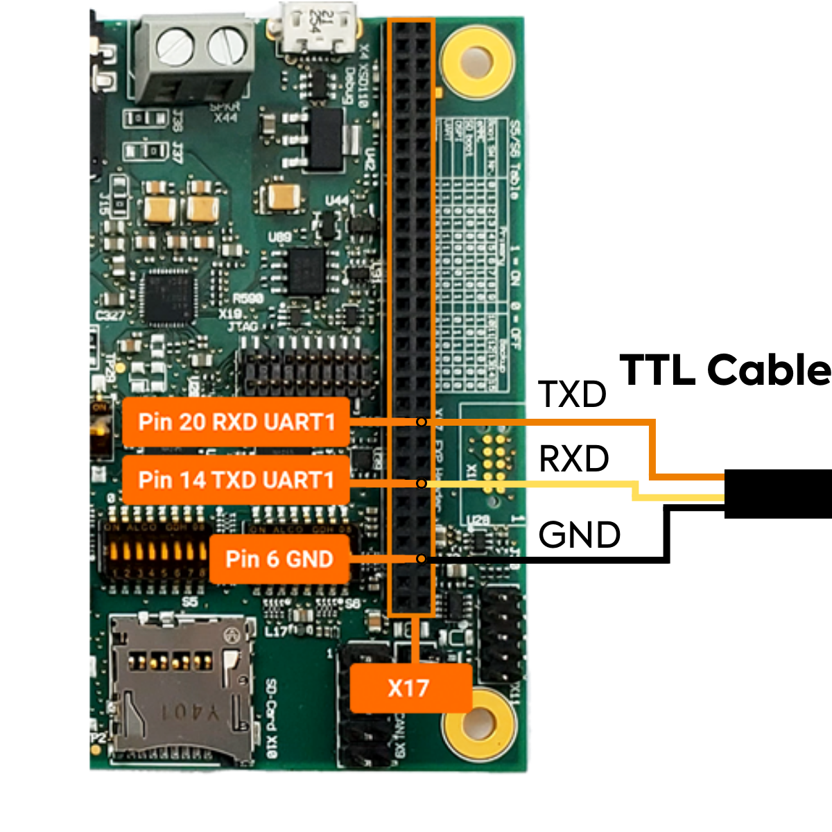
Connect the TTL Cable to the expansion header X17. Do not connect the cable to your host system yet.
GND |
Black Connecter |
Pin 6 (X17) |
|---|---|---|
TXD |
Orange Connecter |
Pin 14 (X17) |
RXD |
Yellow Connecter |
Pin 20 (X17) |
Power the development kit back on.
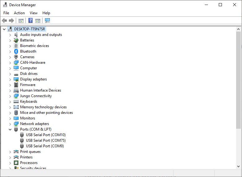
Open your host system’s Device Manager and expand Ports (COM & LPT).
Note
Windows systems can press the Windows key, type “device manager” and press ENTER.
Connect the USB end of the TTL cable to the Host machine.
Take note of any new device names that appear under “Ports”. You’ll need the COM port device number in the next steps.
Terminal Setup
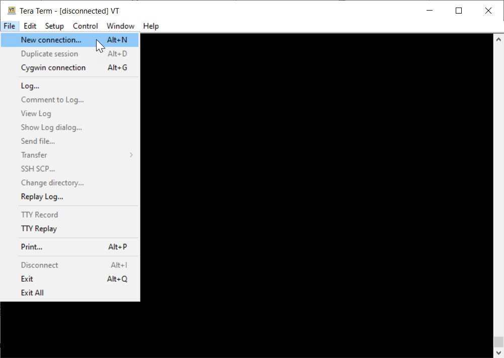
Open a new terminal window. This guide will be using TeraTerm but other emulators like PuTTY will work as well.
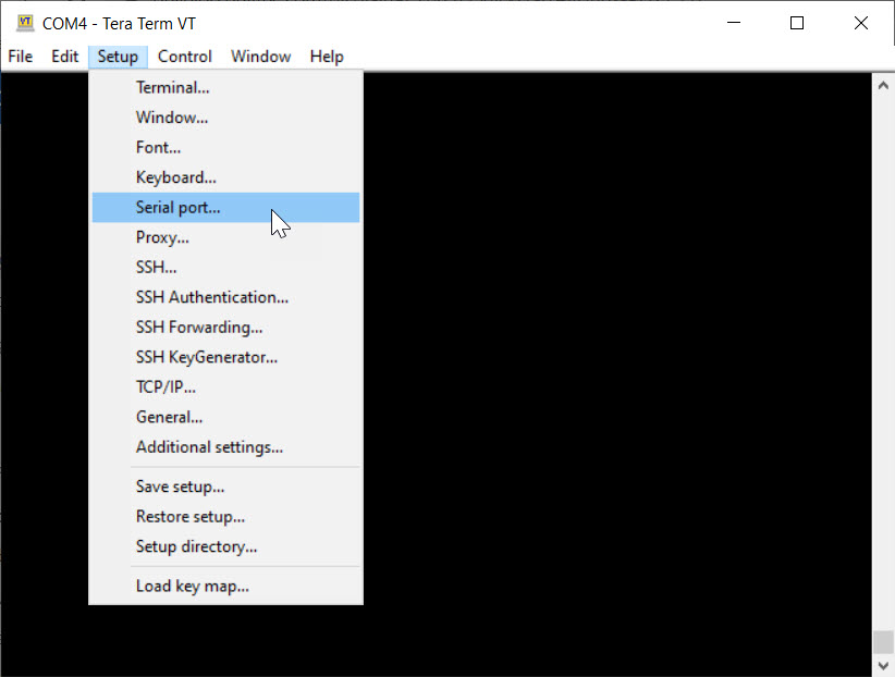
Set the serial parameters: 115200 Baud, 8 bit data, no parity bits, 1 stop bit and no flow control.
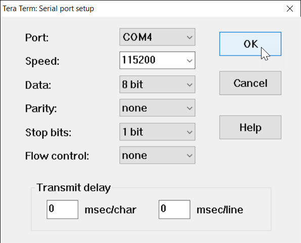
Select a COM port that corresponds to the TTL cable.
Setting the Baud Rate
In the terminal window connected to X49, the development kit default serial port, enter the following to set the communication rate for UART0:
Target (Linux)stty -F /dev/ttyS3 115200
Sending a Message to UART1
Now try sending a message to UART1 terminal. In the debug console terminal, enter the following command:
Target (Linux)echo You did it! > /dev/ttyS3
Take a look at the UART1 terminal.
Expected Output (UART1 Console)You did it!
Note
If you have trouble receiving or sending messages to a console terminal, ensure that you have the correct COM port set and the terminal is configured for 8 bit data, no parity bits, 1 stop bit, and a baud rate of 115200.
You can ensure the COM port settings in the debug console with the following command:
To set the settings to match that of the debug console use the following command:
Target (Linux)stty -F /dev/ttyS3 115200 stty -brkint ixoff -imaxbel iutf8 -iexten < /dev/ttyS3
Receiving a Message from UART1
To read messages from UART1, set your debug console to output any incoming data from the UART1 connection:
Target (Linux)cat /dev/ttyS3
Now send a message from the UART1 console to the debug console. Type anything you want and then hit the “Enter” button.
Expected Outputroot@phyboard-lyra-am62xx-2:~# cat /dev/ttyS3 Hello World
Enter Ctrl + C in the Linux console to stop waiting for incoming data.