GPIO
The GPIO pin numbering of the phyCORE-AM62Ax schematic is represented differently from the device identifier used by the kernel. To learn more information about the phyCORE-AM62Ax GPIO interface, please see section 10.2 in the Hardware Manual.
Requirements
M/M Jumper Wire Optional for Advanced Steps
Note
The expansion header was designed for 2mm pins. It is acceptable to use 2.54mm jumper pins during the development and verification of interfaces. The only issue arises when you switch back to plugging in a 2mm male header for an expansion board you created.
Using LEDs and Push Buttons
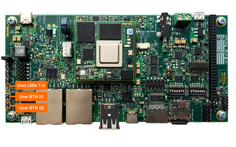
This section of the guide will go over the use of the LEDs and Push buttons populated on the phyBOARD-Lyra carrier board, see the User Interface section of the schematic for more information. These User Interface signals are all assigned to kernel drivers within the arch/arm64/boot/dts/ti/k3-am62axx-phyboard-lyra.dtsi.
Toggling the User LEDs
The development kit has two user-configurable LEDs (D24 and D7). User LED1 is connected to GPIO0_32 and user LED2 is connected to the GPIO Expander.
GPIO0_32/GPIO2_LED2 is represented as gpio-452/gpio-326 in software. In the next section “GPIO Signal Naming” you’ll see that these GPIO signals are already allocated to names led-1/led-2. This indicates that a driver has claimed these gpios, and this can be confirmed by checking the linux device tree. The driver is gpio-leds.
Let’s take a look at the sysfs interface that the gpio-leds driver are located in.
ls /sys/class/leds/
root@phyboard-lyra-am62axx-1:~# ls /sys/class/leds/
green:heartbeat@  led-1@  led-2@  mmc0::@  mmc1::@
Let’s first turn ON the LED (it should be OFF by default):
echo 1 > /sys/class/leds/led-1/brightness
Warning
When the gpio-leds driver is attached to a PWM enabled pin, the brightness file will actually control the physical brightness of the pin and allow you to write values from 0 to 255 to do so. In this case, GPIO0_32 is not PWM capable pin and thus 0 corresponds to the LED being OFF and any other value sets the LED to ON.
Turn OFF the LED
echo 0 > /sys/class/leds/led-1/brightness
We can also leverage the driver to do more interesting things with the LED. Let’s configure the GPIO as a Linux heartbeat for example:
echo "heartbeat" > /sys/class/leds/led-1/trigger
The heartbeat trigger can be turned OFF like so:
echo "none" > /sys/class/leds/led-1/trigger
The other LED, led-2, can be controlled in the same way.
GPIO Signal Naming
The GPIO pin numbering of the phyCORE-AM62Ax schematic is represented differently from the device identifier used by the kernel. Therefore in GPIO hardware signal naming convention looks very different from the software GPIO naming convention. This section will walk through how to calcualte the GPIO signals and shoe how to identify which GPIO signals are in use on the developmeny kit.
Active GPIO Signals
See which GPIO signals have been allocated by running the following command.
cat /sys/kernel/debug/gpio
root@phyboard-lyra-am62axx-1:~# cat /sys/kernel/debug/gpio
gpiochip2: GPIOs 360-367, parent: i2c/1-0021, pcf8574, can sleep:
gpio-360 (GPIO0_HDMI_RST      |reset               ) out hi ACTIVE LOW
gpio-361 (GPIO1_CAN0_nEN      |standby             ) out lo
gpio-362 (GPIO2_LED2          |led-2               ) out lo
gpio-363 (GPIO3_LVDS_GPIO     )
gpio-364 (GPIO4_BUT2          |menu                ) in  lo IRQ
gpio-365 (GPIO5_LVDS_BKLT_EN  )
gpio-366 (GPIO6_ETH1_USER_RESE)
gpio-367 (GPIO7_AUDIO_USER_RES)

gpiochip1: GPIOs 368-419, parent: platform/601000.gpio, 601000.gpio:
gpio-391 (                    |home                ) in  lo

gpiochip0: GPIOs 420-511, parent: platform/600000.gpio, 600000.gpio:
gpio-433 (                    |green:heartbeat     ) out lo
gpio-452 (                    |led-1               ) out lo
gpio-460 (                    |gpio-fan            ) out lo ACTIVE LOW
GPIO SOC Modules |
GPIO Hardware Signal |
Section |
|---|---|---|
gpiochip2 |
GPIO Expander via I2C |
360-367 |
gpiochip1 |
GPIO1 |
368-419 |
gpiochip0 |
GPIO0 |
420-511 |
Note
If a gpio instance is listed in that above /sys/kernel/debug/gpio file it means that it is tied to an active kernel driver. If this is the case, you shouldn’t not attempt to control the gpio unless using the appropriate userspace tools, provided by the hardware driver. This guide will outline the control of gpios both tied to a kernel driver and those that are unused, left in reset.
Note gpio-460 will appear when the fan device tree overlay is active. Please see the Fan guide for more information.
Calculating GPIO Signal Names
This section of the guide will walk through how to figure out the hardware signal name and the corresponding SOC GPIO signal name.
Hardware to Software
Using the development kit’s carrier board and SOM schematics the hardware GPIO signal GPIO0_32 (LED1) at SOM connector C15 pin.
See which GPIO signals have been allocated by running the following command.
cat /sys/kernel/debug/gpio
root@phyboard-lyra-am62axx-1:~# cat /sys/kernel/debug/gpio
gpiochip2: GPIOs 360-367, parent: i2c/1-0021, pcf8574, can sleep:
gpio-360 (GPIO0_HDMI_RST      |reset               ) out hi ACTIVE LOW
gpio-361 (GPIO1_CAN0_nEN      |standby             ) out lo
gpio-362 (GPIO2_LED2          |led-2               ) out lo
gpio-363 (GPIO3_LVDS_GPIO     )
gpio-364 (GPIO4_BUT2          |menu                ) in  lo IRQ
gpio-365 (GPIO5_LVDS_BKLT_EN  )
gpio-366 (GPIO6_ETH1_USER_RESE)
gpio-367 (GPIO7_AUDIO_USER_RES)

gpiochip1: GPIOs 368-419, parent: platform/601000.gpio, 601000.gpio:
gpio-391 (                    |home                ) in  lo

gpiochip0: GPIOs 420-511, parent: platform/600000.gpio, 600000.gpio:
gpio-433 (                    |green:heartbeat     ) out lo
gpio-452 (                    |led-1               ) out lo
gpio-460 (                    |gpio-fan            ) out lo ACTIVE LOW
Looking at the section “gpiochip0”, since it translates to GPIO0, you can see the first software GPIO signal is gpio-420 for GPIO0. By adding 420 and the hardware signal(GPIO0_32) together the proper software singal name can be found.
420+32 = 452
Now you know that gpio-452 (software) is GPIO0_32 (hardware).
Software to Hardware
In order to figure out which hardware GPIO signals are already allocated simply subtract the software GPIO singal from the GPIO bank starting section.
Find the GPIO bank section by running the following command on the development kit.
Target (Linux)cat /sys/kernel/debug/gpio
The GPIO0 bank correlates gpiochip0 which starts at gpio-420. To find which hardware GPIO signal led-1 corresponds to gpio-452, subtract gpio-420 from the start of the GPIO bank (gpio-420).
452-420 = 32
Now you know that gpio-452 (software) is GPIO0_32 (hardware).
Advanced GPIO Control
Export a GPIO
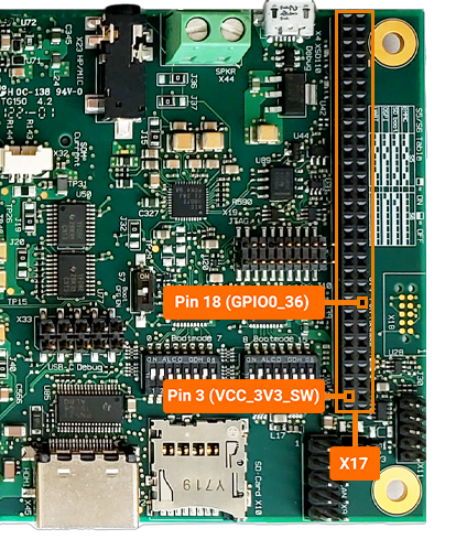
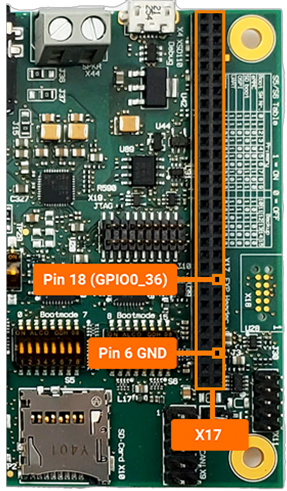
Thus far in this guide we have gone over the control of GPIOs assigned to specific gpio-X drivers within the kernel, now let’s look into exporting and controlling unused GPIOs. For this guide we will target GPIO0_36 which is brought out to pin 18 of the X17 expansion connector.
First, convert the hardware resource GPIO0_36 into it’s software representation. We should come up with GPIO0_36 = gpio-456 in Linux.
Export this GPIO in the kernel:
echo 456 > /sys/class/gpio/export
This will create a new sysfs directory /sys/class/gpio/gpio456 (note that this step will not work for GPIOs already reserved by a driver).
Let’s navigate into the new directory and take a look around:
cd /sys/class/gpio/gpio456
ls
Similar to the features exposed by the gpio-leds driver outlined above in this guide, exporting GPIOs within sysfs creates a directory full of files that enable us to control the GPIO from userspace. We can check the current configuration of the GPIO interface by reading some of these files:
cat direction
cat value
cat active_low
root@phyboard-lyra-am62axx-1:gpio456# cat direction
in
root@phyboard-lyra-am62axx-1:gpio456# cat value
0
root@phyboard-lyra-am62axx-1:gpio456# cat active_low
0
Take a look at the pad config on the development kit:
Target (Linux)devmem2 0x000F4094
Expected Outputroot@phyboard-lyra-am6a2xx-1:gpio456# devmem2 0x000F4094 /dev/mem opened. Memory mapped at address 0xffff98e0c000. Read at address 0x000F4094 (0xffff98e0c094): 0x08214007
Multiplex the signal as a pulldown input GPIO using a direct register write (this is only recommended for testing).
Target (Linux)devmem2 0x000F4094 w 0x08244007
Similar to the features exposed by the gpio-leds driver outlined above in this guide, exporting GPIOs within sysfs creates a directory full of files that enable us to control the GPIO from userspace. We can check the current configuration of the GPIO interface by reading some of these files:
Target (Linux)cat direction cat value cat active_low
Expected Outputroot@phyboard-lyra-am62axx-1:gpio456# cat direction in root@phyboard-lyra-am62axx-1:gpio456# cat value 1 root@phyboard-lyra-am62axx-1:gpio456# cat active_low 0
You could go ahead and short GPIO0_36 (pin 18 of X17) to VCC_3V3_SW (pin 3 of X17) to simulate a button press and at the same time read the value file to see it go from 0 to 1.
Export and Control a Output GPIO
Let’s take a closer look at this GPIO:
In order to fully control GPIOs, we will need to have a understanding of the way the AM62Ax processor is designed at the silicon level. The AM62Ax processor has many subsystems within it while having a limited number of processor pads to bring out signals to and enable hardware interfaces on (such as USB, mPCIe, GPIOs, etc). These various hardware subsystems share processor pins and the processor pins have to be configured for the signal you want to access. This is a process called pin multiplexing (or just pin muxing) and is the reason that you won’t ever be able to bring out every feature the AM62Ax processor has to offer all at the same time (you have to make decisions regarding which interfaces are critical to your application and design and ensure they can all come out, without conflicting).
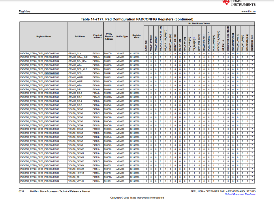
Since we are ultimately trying to control the GPMC0_BE1n processor pad (this is the processor pin that brings out GPIO0_36 in the phyCORE-AM62Ax development kit schematic) lets look this up in the processor datasheet.
Here we can confirm the processor pin (often referred to as a processor ball, or pad as well) is number K18 (which should agree with the SOM schematic), the pad’s config register’s name is PADCONFIG37, the pad config register address is 0x000F4094, and the mux mode we want for GPIO0_36 is 7.
Let’s take a look at the pad config on the development kit:
devmem2 0x000F4094
root@phyboard-lyra-am62axx-1:gpio435# devmem2 0x000F4094
/dev/mem opened.
Memory mapped at address 0xffffb05db000.
Read at address  0x000F4094 (0xffffb05db0a8): 0x08244007
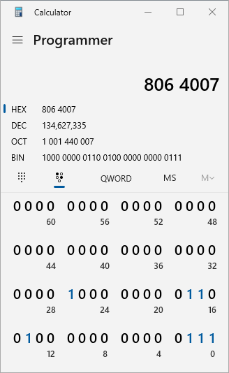
The 0x000F4094 memory address contained the data 0x08244007.
A handy trick to decode that hexadecimal output is to use your Windows Host Machine’s Calculator App and setting it to Programmer mode.
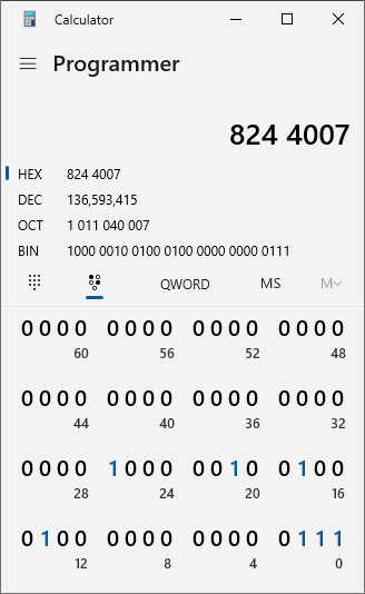
We can use the bit toggling keypad to view the individual bits that are set, as well as change them easily.
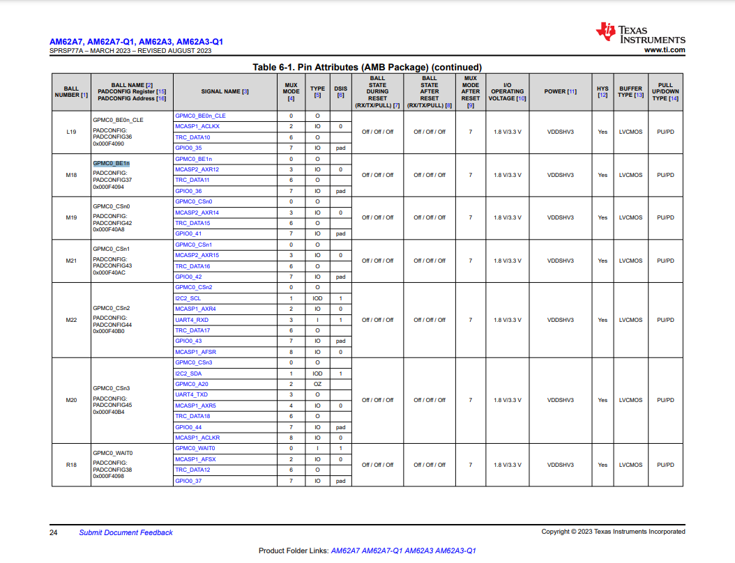
Next, lookup PADCONFIG37 within the AM62Ax processor Technical Reference Manual (TRM) from Texas Instruments. You should find the following table breaking down what each bit within the pad config register means.
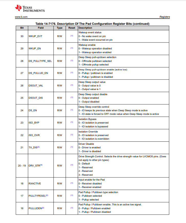
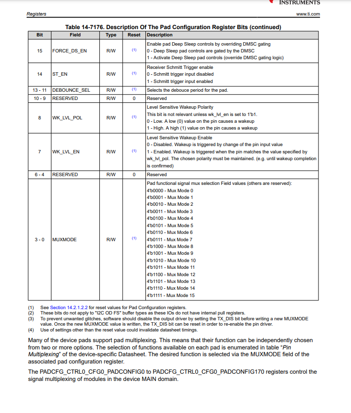
Looking at the data stored in 0x000F4094 alongside the TRM’s Table 6-2045, we can see that the processor pin has a default state of 0x08214007 but in the section above it was set to 0x08244007. The new setting can be interpreted as follows:
Deep Sleep pull-up/down Disabled
TX (transmit) Driver Disabled
RX (receive) Driver Enabled
Pulldown Enabled
Receiver Schmitt Trigger Enable
Mux Mode 7
We can see that the processor pin by default is sitting in a state that doesn’t make it very convenient for us to export the GPIO in sysfs.
We’ll need to modify the GPIO in sysfs AND modify the processor’s pad config!
First, let’s mux the processor pad to function as a output GPIO0_36. We’ll want to set 0x000F4094 to reflect the following to do this (other options such as the internal pull up/down resistors could be optionally enabled depending on your needs):
TX (transmit) Driver Enabled
RX (receive) Driver Enabled
Pullup Enabled
Receiver Schmitt Trigger Enable
Mux Mode 7
This will correspond to the value 0x08064007.
Write the value 0x08064007 to PADCONFIG37:
Target (Linux)devmem2 0x000F4094 w 0x08064007
Now our pin is properly configured to function as an output (for driving an LED for example).
Next, we need to configure the kernel to use this pin as a output:
Target (Linux)echo out > direction
Connect an LED on a breadboard to the expansion header X17 pin 18 and 6.
With both the kernel and hardware interface properly configured as an output, we can now successfully drive the pin:
echo 1 > value
echo 0 > value