SPI
The Serial Peripheral Interface (SPI) is a transmit/receive, master/slave synchronous serial bus. The phyCORE-AM67x SOM provides access to four SPI ports at the phyCORE-Connector. This guide will show you how to test the SPI interface on the phyCORE-AM67x development kit carrier board via a loopback test. To learn more information about the phyCORE-AM67x SPI, please see section 7.4 in the Hardware Manual.
Warning
The phyBOARD-Rigel AM67x needs additional muxing to use SPI and the MCU_SPI EEPROM. The SPI0 pins are currently muxed to be used in different modes, and the MCU_SPI0 is not muxed to be accessible to linux by default. To use SPI0 as shown in this example, you need to mux the SPI0 pins as SPI0 signals in the device tree.
Requirements
Jumper Wire Male to Male
Development Kit Setup
Note
There are 2x SPI interfaces on the phyCORE-AM67x SOM but only one is set up for use on the development kit carrier board (SPI0).
Power off and remove the power supply from the development kit.
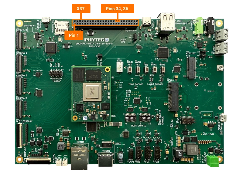
sh-phyboard-rigel-am67xx-1:~# poweroffConnect pin 34 and pin 36 of the X37 expansion connector using a M-M jumper wire. These pins correspond to SPI0’s MISO and MOSI signals.
Loop-back Test
Initiate the loop-back test on the SPI 0 interface (/dev/spidev 1.0)
sh-phyboard-rigel-am67xx-1:~# spidev_test -v -D /dev/spidev1.0
spi mode: 0x0
bits per word: 8
max speed: 500000 Hz (500 KHz)
TX | FF FF FF FF FF FF 40 00 00 00 00 95 FF FF FF FF FF FF FF FF FF FF FF FF FF FF FF FF FF FF F0 0D  | ......@....�..................�.
RX | FF FF FF FF FF FF 40 00 00 00 00 95 FF FF FF FF FF FF FF FF FF FF FF FF FF FF FF FF FF FF F0 0D  | ......@....�..................�.
Note
If SPI communication is not functioning properly, only “00”s or “FF”s will be printed in the “rx data”.
This can be demonstrated by running the previous command again with the wire removed.