Industrial Ethernet Dev Kit
This wiki section contains information on how to run demo software for industrial Ethernet communication on the PHYTEC phyBOARD-Electra AM64x.
The demos support these communication protocols:
EtherCAT SubDevice (slave)
PROFINET Device
EtherNet/IP Adapter
The required software/firmware components are provided in binary form for the demo. To communicate with the device an external EtherCAT MainDevice (Master), PROFINET Controller or EtherNet/IP Scanner is required.
By default the demo uses the PHYTEC Ethernet Expansion Board ports ETH3 and ETH4. Using ETH1 and ETH2 on the carrier board is supported, too.
Requirements
In order to follow this guide, you will need:
The phyBOARD-Electra AM64x Industrial Ethernet Dev Kit. This includes:
phyCORE-AM64x System on Module
phyBOARD-Electra AM64x carrier board
PHYTEC Ethernet Expansion Board KPEB-C-010 (optional)
Micro-USB cable
3 Ethernet cables
Pre-flashed bootable SD card (BSP-Yocto-EdgeAI-AM68x-v0.2)
12V/2A power supply
USB microSD card reader
When using ETH1 and ETH2 of the carrier board, note that the board must be configured to use MII. Check/resolder the jumpers J26 and J27 to use MII (pins 2+3 (TX_CLK), reference phyBOARD-Electra AM64x MII Jumper Setting for the correct placement).
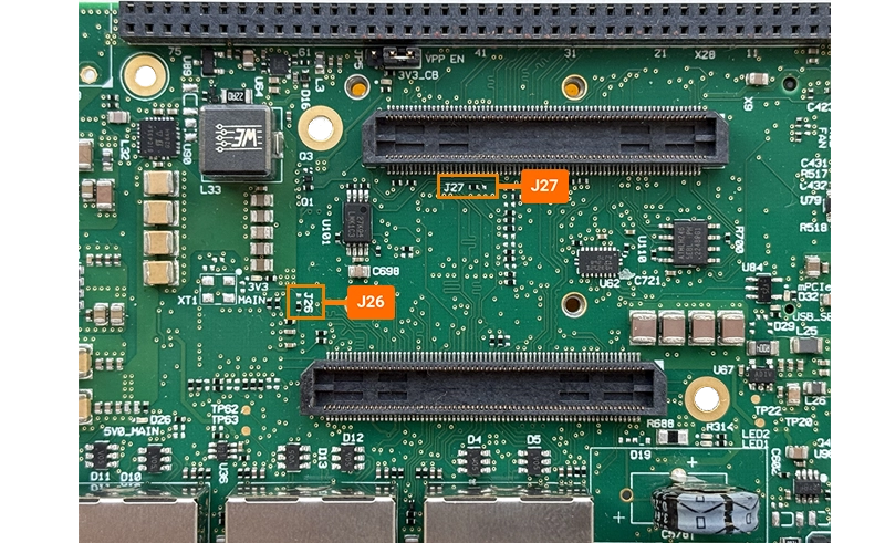
phyBOARD-Electra AM64x MII jumper settings
Follow the Quickstart to boot into the BSP-Yocto-EdgeAI-AM68x-v0.2 Linux using the supplied SD card.
Assign a static IP address to eth0 as described here
Setup
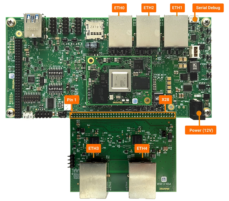
Connect ETH0 to the Ethernet network
When using PHYTEC Ethernet Expansion Board:
Connect the expansion board as shown
Connect ETH3 to the industrial Ethernet controller node
When NOT using PHYTEC Ethernet Expansion Board (carrier board ports):
Connect ETH1 to the industrial Ethernet controller node
Connect the Micro-USB cable to the DEBUG_UART connector
Step 1: Setup device tree overlays
To access the Ethernet interfaces from the R5F core, these interfaces must not be claimed by Linux.
Therefore, apply the device tree overlays available in /boot.
When using PHYTEC Ethernet Expansion Board, replace the content with the line
overlays=k3-am642-phyboard-electra-ind-eth-demo_r5f.dtbo k3-am642-phyboard-electra-ind-eth-demo_icssg1.dtbo
When NOT using PHYTEC Ethernet Expansion Board (carrier board ports), replace the content with the line
overlays=k3-am642-phyboard-electra-ind-eth-demo_r5f.dtbo k3-am642-phyboard-electra-ind-eth-demo_icssg0.dtbo
Reboot
Note
Enabling via u-boot environment is of course alternatively possible, i.e.
sh-uboot:~# setenv overlays k3-am642-phyboard-electra-ind-eth-demo_r5f.dtbo k3-am642-phyboard-electra-ind-eth-demo_icssg0.dtbo
sh-uboot:~# saveenv
sh-uboot:~# boot
Tip
For the PHYTEC Ethernet Expansion Board, ICSSG1 is disabled, for the carrier board ethernet ports, ICSSG0 is disabled. You may decide to disable both to be flexible in using either port:
overlays=k3-am642-phyboard-electra-ind-eth-demo_r5f.dtbo k3-am642-phyboard-electra-ind-eth-demo_icssg0.dtbo k3-am642-phyboard-electra-ind-eth-demo_icssg1.dtbo
Step 2: Start the application
When using PHYTEC Ethernet Expansion Board
Use the firmware binary located at
/lib/firmware/ibv-indcomms/<ethercat, ethernetip or profinet>/Release_ETHEXT/
When NOT using PHYTEC Ethernet Expansion Board (carrier board ports)
Use the firmware binary located at
/lib/firmware/ibv-indcomms/<ethercat, ethernetip or profinet>/Release_ETHCAR/
To load and run the R5F firmware, run:
sh-phyboard-electra-am64xx-2:~# cd phytec_ibv_indcomms_example
# for EtherCAT
sh-phyboard-electra-am64xx-2:~# ./start-r5.sh /lib/firmware/ibv-indcomms/ethercat/Release_ETHCAR/ethercat_subdev_beckhoff_electra.out

# for Ethernet/IP
sh-phyboard-electra-am64xx-2:~# ./start-r5.sh /lib/firmware/ibv-indcomms/ethernetip/Release_ETHCAR/ethernetip_adapter_electra.out

# for PROFINET
sh-phyboard-electra-am64xx-2:~# ./start-r5.sh /lib/firmware/ibv-indcomms/profinet/Release_ETHCAR/profinet_dev_electra.out
Adopt path when using the carrier board ports!
Check for the following output:
[  91.259092] remoteproc remoteproc0: powering up 78000000.r5f
[  91.298590] remoteproc remoteproc0: Booting fw image profinet_dev_electra.out, size 3213032
[  91.306355] rproc-virtio rproc-virtio.5.auto: assigned reserved memory node r5f-dma-memory@a0000000
[  91.310681] virtio_rpmsg_bus virtio1: rpmsg host is online
[  91.313839] rproc-virtio rproc-virtio.5.auto: registered virtio1 (type 7)
[  91.313868] remoteproc remoteproc0: remote processor 78000000.r5f is now up
[  91.323525] virtio_rpmsg_bus virtio1: creating channel rpmsg-raw addr 0xd
[  91.327161] virtio_rpmsg_bus virtio1: creating channel rpmsg-raw addr 0xe
Run the Linux application
# for EtherCAT
sh-phyboard-electra-am64xx-2:~# ./ind_comms_linux_demo

# for Ethernet/IP
sh-phyboard-electra-am64xx-2:~# ./ind_comms_linux_demo -f enip-flash.bin

# for PROFINET
sh-phyboard-electra-am64xx-2:~# ./ind_comms_linux_demo -f pn-flash.bin
-m sets the MAC address for the interface (not used in EtherCAT firmware), may be omitted
-f supplies the file for non-volatile memory emulation, may only be omitted for EtherCAT (not used in EtherCAT firmware).
Note
The ind_comms_linux_demo application must be run to fully initialize the R5F firmware. The industrial ethernet protocol is not available until this application is started. The application may be stopped after initialization, the firmware will continue to run.
The terminal shows a screen of the demo application:
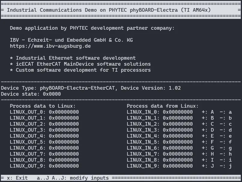
Values of process data variables (outputs) which are provided to Linux by the controlling application
Values of process data variables (input) which are defined by Linux and provided to the controlling application. The values can be incremented and decremented with pressing the keys A … J and a … j .
Furthermore, these signal inputs/output are managed by the R5F software and provided to/set by the controlling application:
ADC_IN: Value of 12bit analog in channel (connector X27, pin 43)
GPIO_IN: State of the GPIO (connector X27, pin 30)
GPIO_OUT: Output to control an LED on the phyBOARD-Electra AM64x (LED1)
Reboot the board for switching firmware.
EtherCAT SubDevice on phyBOARD-Electra AM64x
Overview
The next diagram gives an overview on the hardware and software architecture to implement an EtherCAT SubDevice based on the phyBOARD-Electra AM64x:
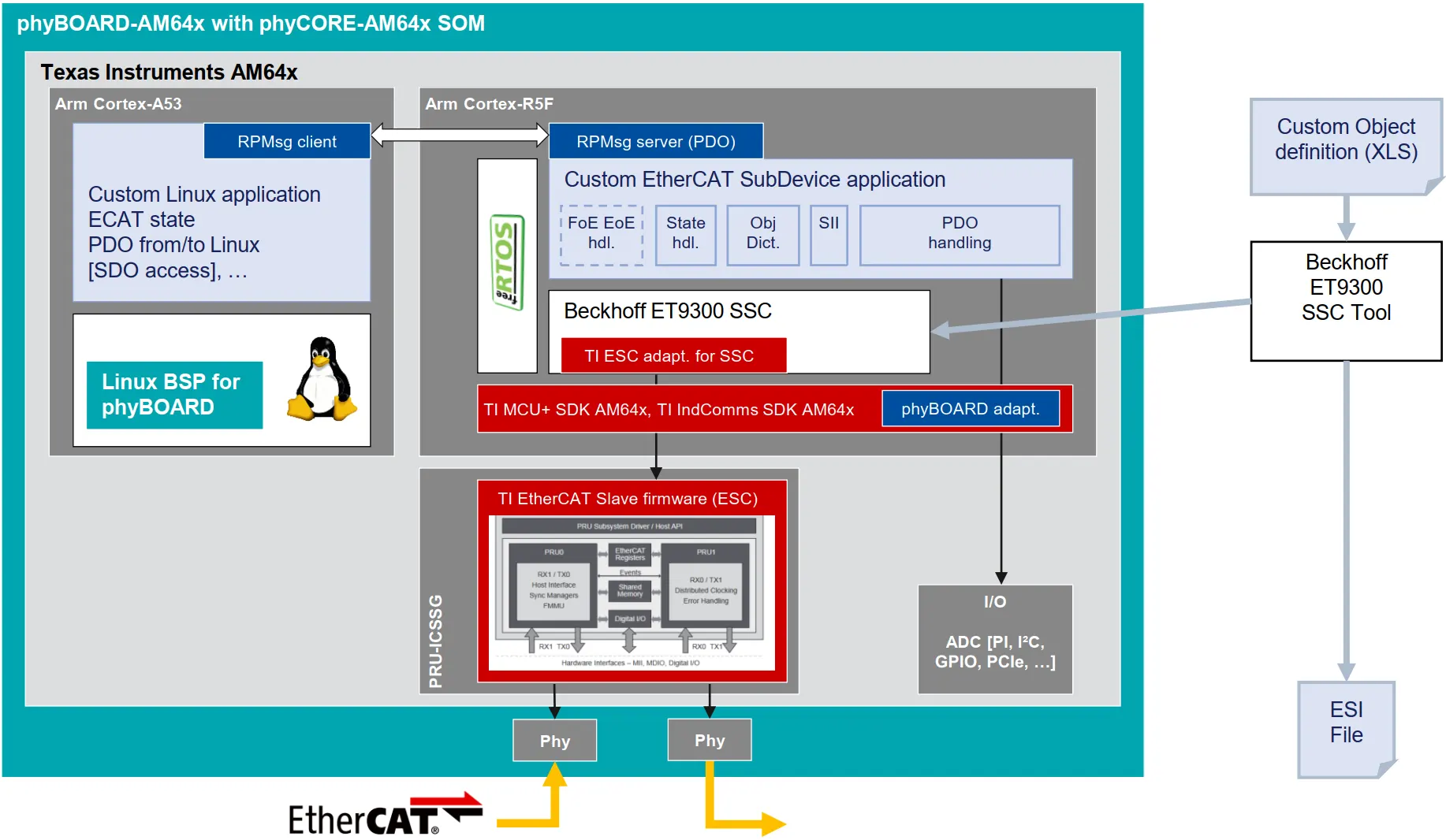
EtherCAT SubDevice architecture on phyBOARD-Electra AM64x
The EtherCAT firmware is started on the AM64x PRU-ICSSG. The firmware is provided by Texas Instruments in the TI Industrial Communications SDK. It supports the low level EtherCAT communication via the two connected Ethernet Phys. See here for the supported EtherCAT features of the TI EtherCAT firmware
On one Arm Cortex-R5F core the EtherCAT SubDevice demo application is running:
The application is based on the Beckhoff SSC sample of TI Industrial Communications SDK. It relies on the TI MCU+SDK and the FreeRTOS operating system. More information about the TI EtherCAT SubDevice sample application
The Beckhoff ET9300 Slave Stack Code (SSC) is integrated to implement an EtherCAT SubDevice. The SSC is available for free for members of the EtherCAT Technology Group
The EtherCAT slave stack can be configured via the Beckhoff ET9300 SSC Tool. The process data objects (PDOs) can be defined by an Excel file. An ESI (EtherCAT Slave Information) file can be exported describing the EtherCAT features and process data of the EtherCAT SubDevice.
The demo application provided in the PHYTEC Industrial Ethernet Dev Package shows how to provide process data as EtherCAT SubDevice. It supports:
A single GPIO output to control an LED
A single GPIO input
Input values which are read from the AM64x ADC
10 output and 10 inputs values which are exchanged via an RPMsg channel with Linux as a sample for data exchange with lower real-time requirements
Linux is running on the Dual-Core Arm Cortex-A53:
Provides a terminal application with access to the 10 outputs and 10 inputs exchanged via RPMsg.
To control the EtherCAT SubDevice application, an EtherCAT MainDevice is necessary. The necessary ESI file for the EtherCAT SubDevice can be found here: demo/ethercat/phyboard-electra-ethercat-subdev-beckhoff.xml
Use Beckhoff TwinCAT as EtherCAT MainDevice
See this guide for using Beckhoff TwinCAT on a PC as an EtherCAT MainDevice to control the EtherCAT SubDevice demo on the phyBOARD-Electra.
Use CODESYS as EtherCAT MainDevice
See this guide for using CODESYS for EtherCAT on a PC as an EtherCAT MainDevice to control the EtherCAT SubDevice demo on the phyBOARD-Electra.
Use IBV icECAT EtherCAT Master Stack
IBV provides a portable EtherCAT MainDevice (master) software which can be licensed in source code for a project.
More information can be found on the icECAT EtherCAT Master product page
A full-featured evaluation version for a Linux PC and for various embedded platforms can be requested at IBV.
EtherNet/IP Adapter on phyBOARD-Electra
The diagram below describes the software architecture implementing the EtherNet/IP Adapter on the phyBOARD-Electra.
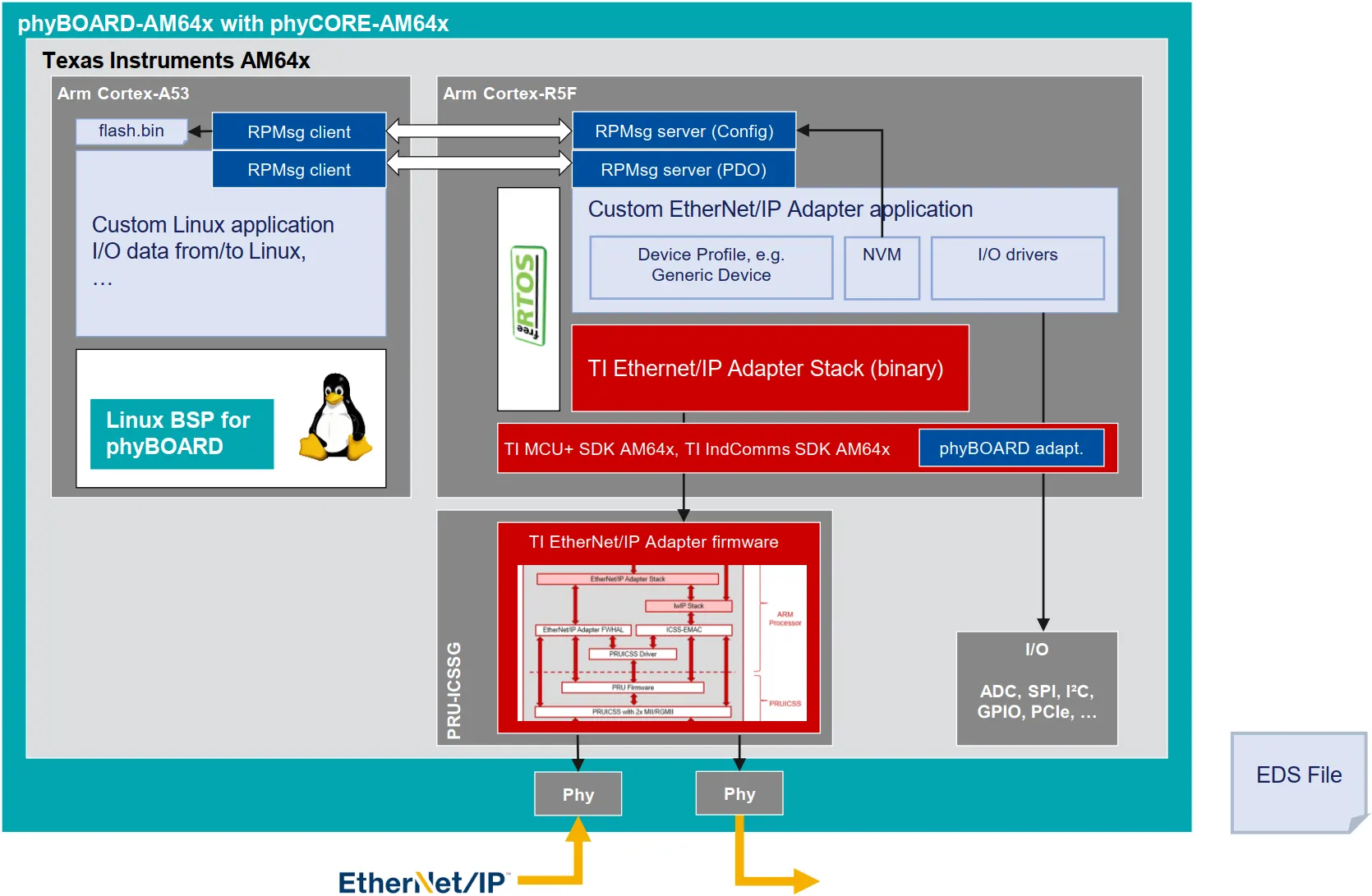
EtherNet/IP Adapter architecture on phyBOARD-Electra
The AM64x PRU-ICSSG is running the TI EtherNet/IP Adapter firmware. This firmware is provided by Texas Instruments in a binary form and loaded to the Programmable Real-Time Unit by the R5F firmware. It implements the switching layer, statistics, DLR (Device Level Ring) and PTP (Precision Time Protocol).
An Arm Cortex-R5F Core runs the EtherNet/IP demo application.
It implements the protocol software stack.
It relies on the TI MCU+SDK and the FreeRTOS operating system. More information about the TI EtherNet/IP Adapter sample application.
EDS files can be generated with the EZ-EDS tool from ODVA
The demo application provided in the PHYTEC Industrial Ethernet Dev Package shows how to provide I/O data as EtherNet/IP Adapter. It supports:
A single GPIO output to control an LED
A single GPIO input
Input values which are read from the AM64x ADC
10 output and 10 inputs values which are exchanged via an RPMsg channel with Linux as a sample for data exchange with lower real-time requirements
The stack stores configuration data in non-volatile memory. This demo emulates an EEPROM through a separate RPMsg channel. The persistent data is stored in a binary file on the Linux system.
Linux is running on the Dual-Core Arm Cortex-A53:
Provides access to the 10 outputs and 10 inputs exchanged via an RPMsg
Provides non-volatile memory emulation (enip-flash.bin)
Provides initial configuration data (MAC)
An EtherNet/IP Scanner is required to run the demo and access the adapter’s I/O data. The required EDS file can be found in demo/ethernetip/phyboard-electra-EthernetIP.eds
Use CODESYS for EtherNet/IP Scanner
See this guide for using CODESYS for EtherNet/IP on a PC as an EtherNet/IP Scanner to control the EtherNet/IP Adapter demo on the phyBOARD-Electra.
PROFINET Device on phyBOARD-Electra AM64x
The PROFINET Device software architecture for the phyBOARD Electra is provided below.
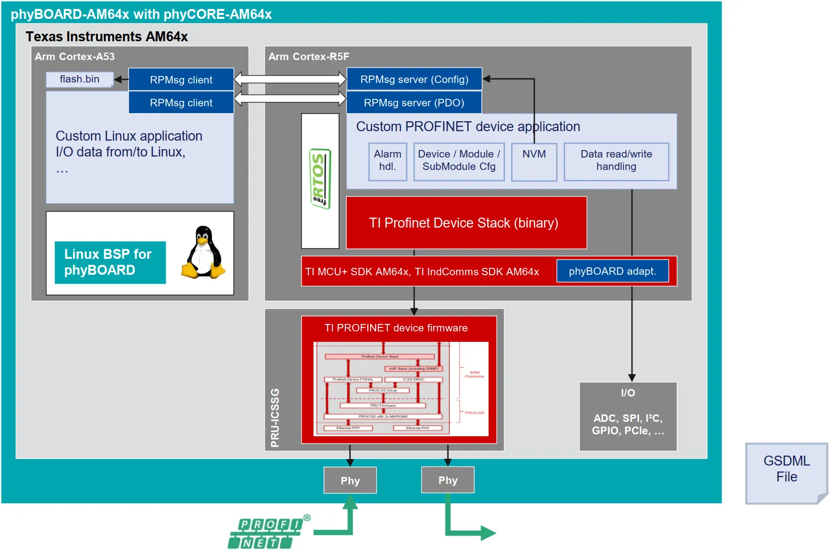
PROFINET Device architecture on phyBOARD-Electra AM64x
The AM64x PRU-ICSSG is running the TI PROFINET device firmware. It is provided by Texas Instruments as a binary. It is based on the SIEMENS ERTEC stack and the LWIP network stack since Industrial Communications SDK v09.02
One Arm Cortex-R5F Core is running the PROFINET device application.
It implements the protocol software stack.
It relies on the TI MCU+SDK and the FreeRTOS operating system. More information about the TI EtherNet/IP Adapter sample application.
GSDML files must be edited manually but can be verified using the PROFINET GSD Checker from the PNO. The GSD Checker currently is only available for members of the PNO/PI.
The demo application provided in the PHYTEC Industrial Ethernet Dev Package shows how to provide I/O data. It supports:
A single GPIO output to control an LED
A single GPIO input
Input values which are read from the AM64x ADC
10 output and 10 inputs values which are exchanged via an RPMsg channel with Linux from data exchange with lower real-time requirements
The application stores configuration data in non-volatile memory. This demo emulates an EEPROM through a separate RPMsg channel. The persistent data is stored in a binary file on the Linux system.
Linux is running on the Dual-Core Arm Cortex-A53:
Provides access to the 10 outputs and 10 inputs exchanged via an RPMsg
Provides non-volatile memory emulation (pn-flash.bin)
Provides initial configuration data (MAC)
Use CODESYS for PROFINET Controller
See this guide for using CODESYS for PROFINET on a PC as PROFINET Controller to control the PROFINET Device demo on the phyBOARD-Electra.
Building your own Industrial Ethernet application
Additionally to a binary delivery, the PHYTEC Industrial Ethernet Dev Package provides sources for building and adapting the demo application. These sources are located in src/. See src/doc/index.html for a comprehensive guide on how to build the demo.
Additional information
Software sources and build instructions:
phyBOARD-Electra AM64x Ethernet Expansion Board Documentation: Ethernet Expansion Board
TI Industrial Communications SDK documentation
Support
As a PHYTEC partner company, IBV - Echtzeit- und Embedded GmbH & Co. KG provides professional engineering services for Industrial Ethernet applications:
Industrial Ethernet SubDevice development and customization
Customization of the data model
Adaptation to a custom application on R5F or Linux
Handling firmware update
Time synchronization (EtherCAT DC, gPTP, …), also with other AM64x controllers and interfaces
Support for conformance test (EtherCAT)
TI MCU+ SDK extensions: driver development, custom board adaptation