WiFi
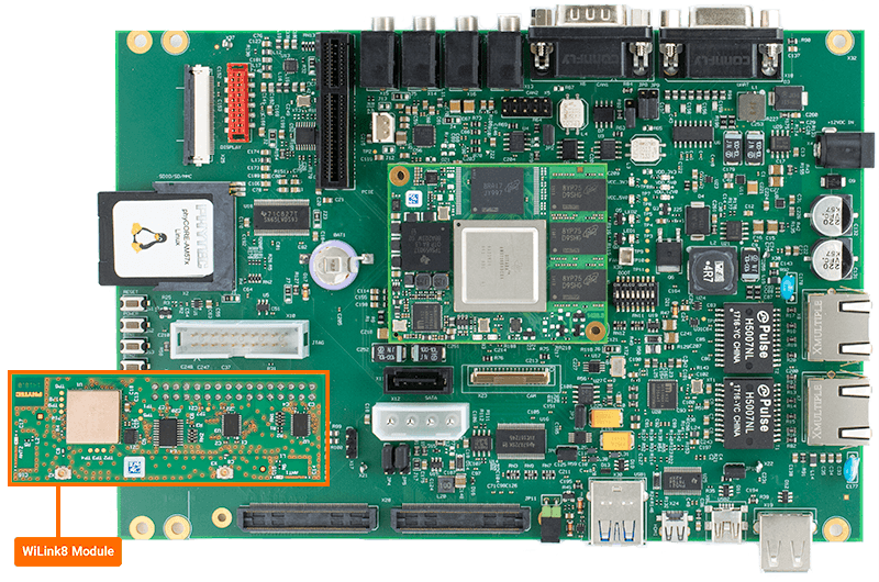
The phyCORE-AM57x development kit does not have Bluetooth integrated on the carrier board, but it can support external Bluetooth modules via the 2x16 pin header (X26). This guide will walk through the basic setup and usage of WiLink8 WiFi module (PCM-949 or PCM-958). For more information on WiFi on the phyCORE-AM57x, please see section 19 in the Hardware Manual.

Requirements
WiFi Module
WiLink8 WiFi Module (PCM-949)
Note
The WiLink8 module can only operate at 2.4GHz. You will need access to a 2.4GHz Wifi network in order to follow this guide and to utilize this module.
Hardware Setup
Power off and remove power from the kit.
Connect the module at X26.
Enable the Bootloader Overlay
The bootloader environment needs to be modified in order to enable the WiFi device tree overlay before booting into Linux.
Power on the development kit and hit any key to stop in U-Boot.
Target (U-Boot)setenv overlays am57xx-phytec-pcm-948-wlan-wilink8.dtbo boot
Note
For more information about overlays see the guide Configuring the Bootloader.
Configure WiFi Credentials
Once in Linux, scan for available networks:
Target (Linux)iw wlan0 scan | grep SSID
Example OutputSSID: OFFICE-GUEST SSID: OFFICE-5GWith a network identified, use wpa_passphrase to create the NETWORK section of your wpa_supplicant-wlan0.conf file with your network credentials and password fille in:
Note
Update “MYSSID” and “passphrase” to the correct credentials for your target network.
mkdir -p /etc/wpa_supplicant
wpa_passphrase MYSSID passphrase > /etc/wpa_supplicant/wpa_supplicant-wlan0.conf
Now we can edit the wpa_supplicant-wlan0.conf to include the rest of our network configuration.
Target (Linux)vi /etc/wpa_supplicant/wpa_supplicant-wlan0.conf
Note
The vi text editor begins in “Command Mode” and you must first hit the ‘i’ key in order to enter “Insert Mode”. Using the arrow keys to navigate, make the necessary changes and then hit ESC to go back to “Command mode”. Now enter “:wq” to write the file and quit.
Pro Tip: Use the right click on your mouse to paste! This will only work if you are in “Insert Mode” first.
      # Giving configuration update rights to wpa_cli
      ctrl_interface=/var/run/wpa_supplicant
      ctrl_interface_group=0
      update_config=1

      # AP scanning
      ap_scan=1

      # ISO/IEC alpha2 country code in which the device is operating
      country=US

      # network section generated by wpa_passphrase
      network={
              ssid="OFFICE-GUEST"
              #psk="123456"
              psk=59e0d07fa4c7741797a4e394f38a5c321e3bed51d54ad5fcbd3f84bc7415d73d
      }
Establish A Connection
Enable the wpa_service for the wlan0 interface:
Target (Linux)systemctl enable wpa_supplicant@wlan0.service
Restart the systemd-networkd and wpa_supplicant services:
Target (Linux)systemctl restart systemd-networkd.service systemctl restart wpa_supplicant@wlan0.service
Confirm wlan0 is connected to the network.
Target (Linux)iw dev wlan0 link
Expected OutputConnected to 6e:d7:9a:cd:92:e9 (on wlan0) SSID: OFFICE-GUEST freq: 2437 RX: 3684015 bytes (18198 packets) TX: 57638 bytes (745 packets) signal: -88 dBm rx bitrate: 39.0 MBit/s tx bitrate: 6.0 MBit/s bss flags: short-preamble short-slot-time dtim period: 1 beacon int: 100
Check the IP address:
Target (Linux)ip addr show wlan0
Expected Output5: wlan0: <BROADCAST,MULTICAST,UP,LOWER_UP> mtu 1500 qdisc fq_codel state UP group default qlen 1000 link/ether c0:ee:40:84:4e:ec brd ff:ff:ff:ff:ff:ff inet 100.55.50.55/24 metric 1024 brd 100.55.50.255 scope global dynamic wlan0 valid_lft 70512sec preferred_lft 70512sec inet6 fe80::c2ee:40ff:fe84:4eec/64 scope link valid_lft forever preferred_lft foreverIn the above example output we can see that this system has been assigned the 100.55.50.55 IPv4 address.
Verify that the WiFi module connected to the network.
Target (Linux)ping -c 5 google.com
Expected OutputPING google.com (142.251.33.110): 56 data bytes 64 bytes from 142.251.33.110: seq=0 ttl=56 time=464.257 ms 64 bytes from 142.251.33.110: seq=1 ttl=56 time=13.316 ms 64 bytes from 142.251.33.110: seq=2 ttl=56 time=15.097 ms 64 bytes from 142.251.33.110: seq=3 ttl=56 time=13.265 ms 64 bytes from 142.251.33.110: seq=4 ttl=56 time=13.039 ms --- google.com ping statistics --- 5 packets transmitted, 5 packets received, 0% packet loss round-trip min/avg/max = 13.039/103.794/464.257 ms
Enabling the Firmware and Building the BSP (Yocto)
An error may occur simular to the error, Direct firmware load for brcm/brcmfmac4373-sdio.phytec,am5728-phytec-pcm-948-40300111I.bin failed with error -2 . Use the following section to select a regdomain and clear the error.
It is required that you select the region when building the BSP in order for the firmware to be included in the Image. Reference this Build the BSP guide to build the BSP image.
Set LWB_REGDOMAIN
From the base Yocto directory we can edit our common.inc file as follows:
Host (Yocto BSP Build)vim sources/meta-ampliphy/conf/distro/common.inc
Un-comment the following line and update the region if necessary:
     # Define Country Code for Laird LWB WiFi chips.
     # Possible Codes: US/CA/ETSI/JP/AU/CN/TW/BR/KR
     # ETSI includes all member countries of the European Union.
     LWB_REGDOMAIN = "US"  #<----- Uncomment this line
A list of regions is shown under Possible Codes for reference.
Rebuild the BSP and proceed.