Quickstart
If you have just purchased a phyCORE-RT1170 development kit, this Quickstart guide will walk you through booting the kit into the Zephyr shell — an interactive terminal interface that allows you to monitor and control the system in real time.
Basic Evaluation Requirements
Minimal setup is required to get started with the phyCORE-RT1170 development kit. For this Quickstart, any modern computer (Windows or Linux) can be used to communicate with the board over a serial terminal and to flash pre-built Zephyr firmware images.
If you plan to build or modify Zephyr applications for the phyCORE-RT1170, a Linux host system with the required development tools is necessary. While a native Linux environment is preferred, installing a Linux Virtual Machine on a Windows system is a practical alternative. For details on the recommended Linux distribution, RAM allocation, and disk space requirements, refer to the Building the Firmware guide.
Check the Board Configuration
The board should have been pre-configured during manufacturing, but we will double check it together as an exercise:
Taking care to avoid Electrostatic Discharge (ESD), press firmly down on the edges of the SOM to ensure that it is fully seated onto the carrier board’s mating connectors.
If evaluating multiple SOM configurations, this will be an important step to perform when swapping between SOMs.
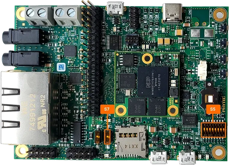
Confirm that switch S7 is set to OFF.
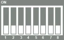
Check that the boot switch S5 is set to boot the system from QSPI Flash.
Serial Communication Setup
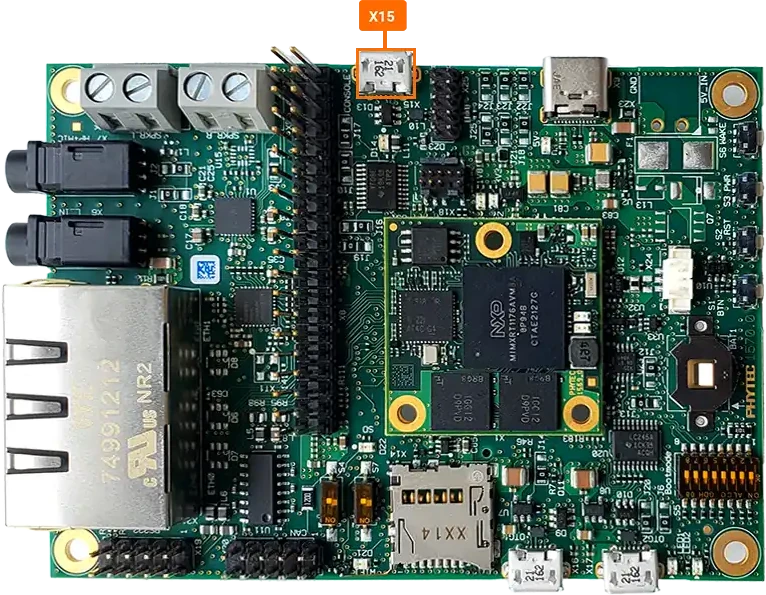
Using the provided micro-USB cable, connect the X15 Serial Debug Port of the phyCORE-RT1170 development kit to an available USB port on your Host Machine.
Windows 11 Instructions
Once the phyCORE-RT1170 development kit is connected to your Windows Host Machine, you will need to determine the COM port in which the serial console will be active on.
Open your Windows Device Manager and expand the “Ports (COM & LPT)” section.
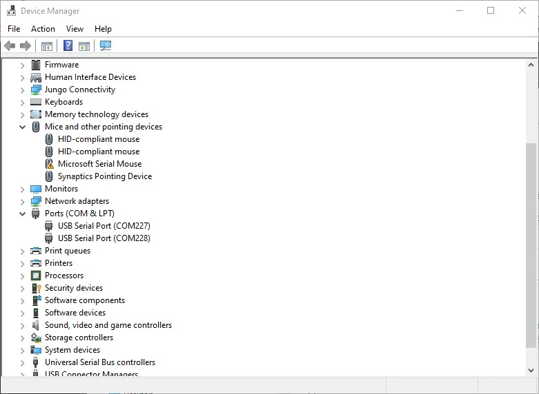
You should see two COM Ports provided by the phyCORE-RT1170 development kit’s FTDI USB to UART Bridge. You will need the lower COM port number in the following steps to establish serial communication with the Zephyr shell running on the target hardware.
Download and open the terminal emulator of your preference. There are many options freely available, such as PuTTY and TeraTerm.
Tip
This guide will use TeraTerm. The User Interface of your terminal emulator will look slightly different depending on which you decide to use, but serial port settings will generally look the same in all terminal emulators.
Create a New Connection using your preferred terminal emulator:
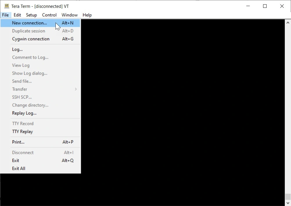
When prompted to configure the connection, specify the connection type as “Serial” and select the COM Port number found in the previous steps.
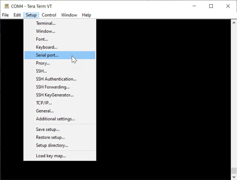
Further setup of your serial connection is usually necessary in TeraTerm. Access the “Serial Port” settings in the “Setup” tab.
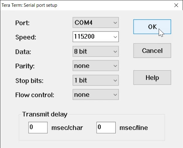
Configure the connection for 115200 Baud, 8 bit data, no parity bits, 1 stop bit and no flow control.
Once you have an empty terminal session, your host system is effectively listening for console data over the COM port you selected. The documentation for the phyCORE-RT1170 (outlined throughout this wiki) will generally refer to this serial session as the “Zephyr Shell” console, as opposed to your Host’s console.
Linux Instructions
Once the phyCORE-RT1170 development kit is connected to your Linux Host Machine, the development kit’s FTDI USB to UART Bridge will come up as two devices; /dev/ttyUSB0 and /dev/ttyUSB1.
Open the serial connection with
minicom(which you may need to install first).sh-host:~$ sudo apt-get update && sudo apt-get install minicom sh-host:~$ minicom -D /dev/ttyUSB0 -b 115200
Alternative command ‘screen’ may also be used.
sh-host:~$ sudo apt-get install screen
sh-host:~$ screen /dev/ttyUSB0 115200
Note
If you have more than 1x USB serial device connected (this could be a second development kit, for example), you will have to determine which /dev/tty* device is specific to your target hardware (otherwise, you may connect to the wrong serial device). Some techniques for determining this include:
Use
dmesgto see which device connected most recently (dmesgwill output all kernel messages andtailjust limits this to the last 10 lines).sh-host:~$ sudo dmesg | tail
Scan the output for your serial device and you will see the specific device enumerator (/dev/tty*) that the kernel assigned to the device.
Alternatively, use the following command to output all serial devices detected by the kernel at once:
sh-host:~$ ls -l /dev/serial/by-id
The output will show which /dev/tty* device enumerator got assigned to each serial device and this has the added benefit of displaying some driver information associated with each device’s serial port. This can be helpful in determining which /dev/tty* file corresponds to which physical piece of hardware.
Power the Board
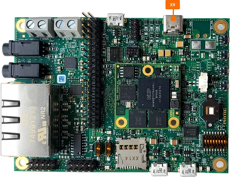
Use the included USB-C 5V power supply to provide power to the phyCORE-RT1170 development kit’s X9 power connector. The system will automatically boot.
Note
Please use the provided power supply with deveopment kit as common USB-C cellphone chargers do not supply the system with enough current.
Run the Blinky Demo
The phyCORE-RT1170 development kit comes preprogrammed with a demo that will initiate a green heartbeat LED on the SOM when system is powered. The system will automatically boot once power is supplied and you should begin to see activity on the serial console.
* Booting Zephyr OS build 301543f8c29d *

uart:~$ kernel version
Zephyr version 4.1.0
uart:~$
Safe Shutdown
Before removing power from the development kit, it is recommend to initiate a safe shutdown whenever possible.
To initiate a safe shutdown, press and hold the power button S3 for 3 seconds.
Once power rail LEDs turn off, it is safe to remove the power supply from the development kit.
Note
For any technical questions, feel free to reach out to PHYTEC’s Support Portal!