Fan
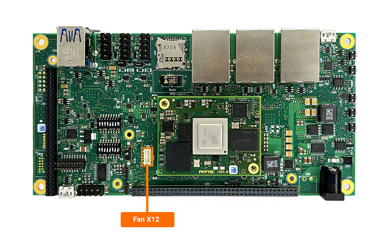
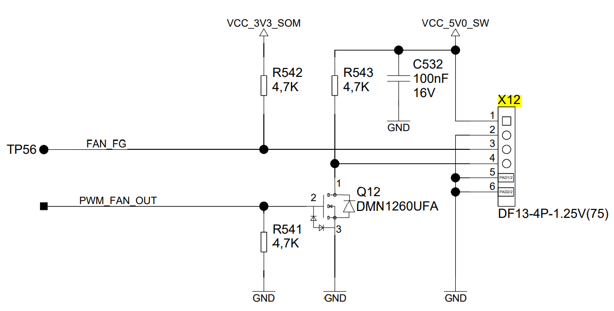
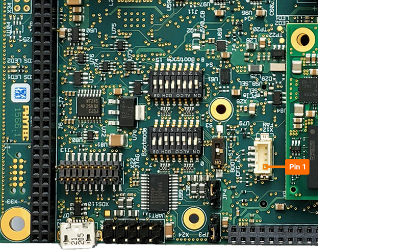
The phyCORE-AM64x development kit provides fan connectivity via a 4-pin Hirose connector at X12 (VCC_5V0_SW rail). The fan is intended to be mounted directly to the processor heat sink for thermal management. The regulated 5V output is enabled by driving GPIO0_28 low (0), turning the fan on. When GPIO0_28 is pulled high (1), the 5V supplied to the fan connector will be turned off. This guide will demonstrate how to test your connections to the header x12. To learn more information about the phyCORE-AM64x thermal management and fan utilization, please see section 4.9 in the Hardware Manual.

Requirements
The phyCORE-AM64x development kit does not include a heat sink and fan. The below is the fan tested on the PHYTEC hardware:
Item |
Description |
Link |
|---|---|---|
Heat Sink |
(29mmx29mmx9.5mm) |
|
Fan |
DC axial fan, 30mm square x 10mm |
|
Female Connector |
4 pin keyed header |
|
Crimping Terminals |
4x crimping jackets |

Recommended Header Configuration
Pin |
Signal |
Wire Color |
|---|---|---|
1 |
VCC_5V0_SW |
Red |
2 |
GND |
Black |
3 |
FAN_FG |
Yellow |
4 |
PWM |
Blue |
Connecting Your Fan
Enabling the Overlay
Power on the development kit and stop in U-boot.
Load the device tree overlay required for exporting the GPIO signal that controls the fan and then boot the board.
Target (U-boot)setenv overlays k3-am64-phyboard-electra-gpio-fan.dtbo boot
Note
For more information about overlays see chapter Configuring the Bootloader.
Verify that the “gpio-fan” was exported properly to gpio-453.
Target (Linux)cat /sys/kernel/debug/gpio
Expected Outputroot@phyboard-electra-am64xx-2:~# cat /sys/kernel/debug/gpio gpiochip1: GPIOs 337-424, parent: platform/601000.gpio, 601000.gpio: gpio-355 ( |PHY reset ) out lo ACTIVE LOW gpio-356 ( |PHY reset ) out lo ACTIVE LOW gpio-379 ( |wp ) out lo gpio-380 ( |spi1 CS1 ) out lo ACTIVE LOW gpiochip0: GPIOs 425-511, parent: platform/600000.gpio, 600000.gpio: gpio-437 ( |green:heartbeat ) out lo gpio-440 ( |red:disk ) out lo gpio-441 ( |green:disk ) out lo gpio-442 ( |home ) in lo gpio-446 ( |menu ) in lo gpio-453 ( |gpio-fan ) out lo ACTIVE LOW gpio-457 ( |standby ) out lo gpio-460 ( |standby ) out lo gpio-488 ( |PHY reset ) out lo ACTIVE LOW
Toggling the Fan
Turn the fan ON.
Target (Linux)echo 1 > /sys/class/thermal/cooling_device0/cur_state
Note
Run the command above 3-4 times to have the fan stay ON consistently.
Turn the fan OFF.
Target (Linux)echo 0 > /sys/class/thermal/cooling_device0/cur_state
Enabling a proper Thermal Governor
If your application includes a GPIO-based fan, PHYTEC recommends enabling the bang-bang thermal governor as the default setting. This governor uses hysteresis to manage fan state transitions, preventing abrupt on/off cycling and enabling smoother control for fans that only support binary on/off operation, rather than variable speed throttling.
Update the current thermal governor strategy to bang-bang using the command below:
Target (Linux)echo bang_bang > /sys/class/thermal/thermal_zone0/policy
Note
To enable the bang-bang thermal governor by default, recompile the kernel with CONFIG_THERMAL_DEFAULT_GOV_BANG_BANG=y in the menuconfig configuration. For further details, please refer to the guide: Modify The BSP.
