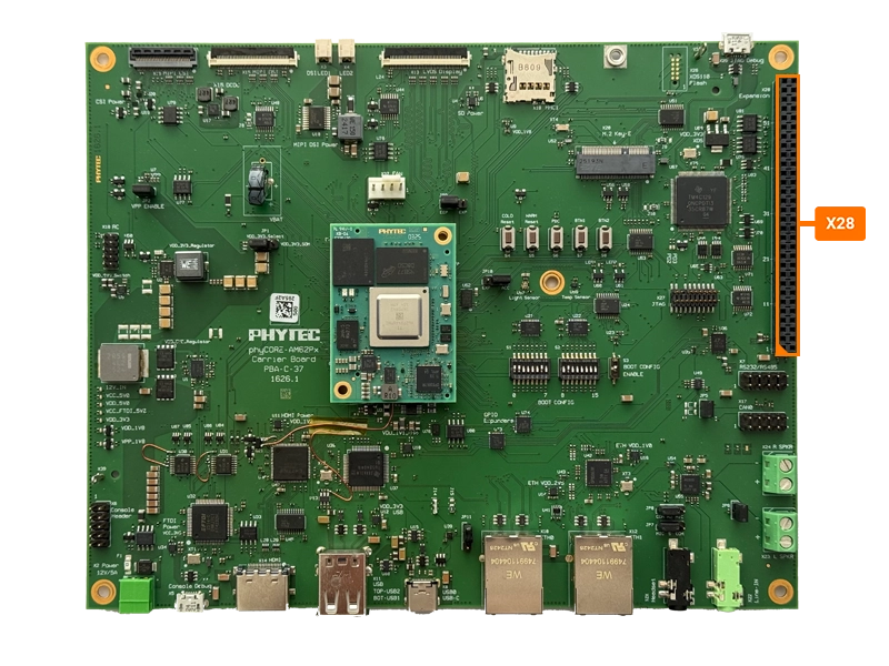
Expansion Connector
The phyCORE-AM62Px development kit provides a 60-pin 2.54mm expansion connector that brings out signals that were either not used elsewhere on the carrier board or were considered useful to have easy access too. For signals not used by either the SOM or the carrier board, they can be freely multiplexed to enable different functionality at the expansion connector. To learn more information about the phyCORE-AM62Px multiplexing, please refer to the Hardware Manual.
Pin Number |
Signal |
Description |
|---|---|---|
1 |
VCC_12V0 |
Main 12.0V input power rail |
2 |
VDD_5V0 |
5.0V Carrier Board power rail |
3 |
VCC_5V0 |
5.0V Main SOM power rail |
4 |
VDD_3V3 |
3.3V Carrier Board power rail |
5 |
VCC_3V3 |
3.3V power rail |
6 |
VDD_1V8 |
1.8V Carrier Board power rail |
7 |
X_WKUP_CLKOUT0 |
WKUP Domain CLKOUT0 output. Only connected to pin D37 on the SOM connector. |
8 |
X_CPSW_ETH0_nINT |
SOM Ethernet PHY Interrupt. Connected to ETH0. |
9 |
X_MCU_SAFETY_ERRORn |
Error signal output from MCU Domain ESM. Only connected to pin C15 on the SOM connector. |
10 |
X_CPSW_ETH0_GPIO_1 |
ETH0 GPIO 1. Connected to ETH0. |
11 |
X_RESETSTATz |
Main Domain warm reset status output. Connected to reset circuit. |
12 |
X_CPSW_ETH0_GPIO_0 |
ETH0 GPIO 0. Connected to ETH0. |
13 |
X_MCU_RESETSTATz |
MCU Domain warm reset status output. Only connected to pin D12 on the SOM connector. |
14 |
X_RTC_EVI |
RTC Event Interrupt. Connected to RTC. |
15 |
PORz_OUT_CONN |
Main Domain POR status output. Connected to reset. |
16 |
X_RTC_INT |
RTC Interrupt. Connected to RTC. |
17 |
GND |
Ground |
18 |
GND |
Ground |
19 |
SPI0_CS0_EXP |
SPI0 Chip Select 0. By default X_MCU_SPI0_CS1 from the SOM is not connected to this pin. |
20 |
X_MCU_SPI0_D1 |
MCU SPI0 Data 1. Connected to SPI EEPROM. |
21 |
X_UART0_RTSN/GPIO1_23/SPI0_CS3 |
GPIO. Only connected to pin D49 of the SOM connector. |
22 |
X_MCU_SPI0_D0 |
MCU SPI0 Data 0. Connected to SPI EEPROM. |
23 |
X_SPI0_CLK |
SPI0 Clock. Connected to accelerometer. |
24 |
X_MCU_SPI0_CLK |
MCU SPI0 Clock. Connected to SPI EEPROM. |
25 |
X_SPI0_D0 |
SPI0 Data 0. Connected to accelerometer. |
26 |
MCU_SPI0_CS1_EXP |
MCU SPI0 Chip Select 1. By default X_MCU_SPI0_CS1 from the SOM is not connected to this pin. |
27 |
X_SPI0_D1 |
SPI0 Data 1. Connected to accelerometer. |
28 |
X_MCU_MCAN1_RX/MCU_GPIO0_16/MCU_SPI0_CS2 |
GPIO. Only connected to pin D69 on the SOM connector. |
29 |
X_MCU_MCAN0_RX/MCU_GPIO0_14 |
GPIO. Only connected to pin D67 on the SOM connector. |
30 |
X_MCU_MCAN1_TX/MCU_GPIO0_15 |
GPIO. Only connected to pin D70 on the SOM connector. |
31 |
X_MCU_MCAN0_TX/MCU_GPIO0_13/MCU_SPI0_CS3 |
GPIO. Only connected to pin D68 on the SOM connector. |
32 |
MCU_I2C0_SCL_CONN |
MCU I2C0 Clock. Connected to I2C buffer on carrier board. |
33 |
I2C0_SCL_CONN |
I2C0 Clock. Connected to I2C buffer on carrier board. |
34 |
MCU_I2C0_SDA_CONN |
MCU I2C0 Data. Connected to I2C buffer on carrier board. |
35 |
I2C0_SDA_CONN |
I2C0 Data. Connected to I2C buffer on carrier board. |
36 |
GND |
Ground |
37 |
GND |
Ground |
38 |
EXP1_GPIO12 |
GPIO expander 1 GPIO12. Connected to the GPIO expander. |
39 |
X_GPMC0_CSn2/GPIO0_43 |
GPIO. Only connected to pin B23 on the SOM connector. |
40 |
EXP1_GPIO13 |
GPIO expander 1 GPIO13. Connected to the GPIO expander. |
41 |
X_GPMC0_CSn3/GPIO0_44 |
GPIO. Only connected to pin B21 on the SOM connector. |
42 |
EXP1_GPIO14 |
GPIO expander 1 GPIO14. Connected to the GPIO expander. |
43 |
X_MCASP0_AXR3/GPIO1_7 |
GPIO. Only connected to pin C32 on the SOM connector. |
44 |
EXP1_GPIO15 |
GPIO expander 1 GPIO15. Connected to the GPIO expander. |
45 |
X_MCASP0_AXR2/GPIO1_8 |
GPIO. Only connected to pin C33 on the SOM connector. |
46 |
EXP1_GPIO16 |
GPIO expander 1 GPIO16. Connected to the GPIO expander. |
47 |
GND |
Ground |
48 |
EXP1_GPIO17 |
GPIO expander 1 GPIO17. Connected to the GPIO expander. |
49 |
X_CPSW_RGMII1_TX_CTL/GPIO0_73 |
RGMII Transmit Control. By default this pin is not connected to the processor on the SOM. |
50 |
X_CPSW_RGMII1_RX_CTL/GPIO0_79 |
RGMII Receive Control. By default this pin is not connected to the processor on the SOM. |
51 |
X_CPSW_RGMII1_TXC/GPIO0_74 |
RGMII Transmit Clock. By default this pin is not connected to the processor on the SOM. |
52 |
X_CPSW_RGMII1_RXC/GPIO0_80 |
RGMII Receive Clock. By default this pin is not connected to the processor on the SOM. |
53 |
X_CPSW_RGMII1_TD0/GPIO0_75 |
RGMII Transmit Data 0. By default this pin is not connected to the processor on the SOM. |
54 |
X_CPSW_RGMII1_RD0/GPIO0_81 |
RGMII Receive Data 0. By default this pin is not connected to the processor on the SOM. |
55 |
X_CPSW_RGMII1_TD1/GPIO0_76 |
RGMII Transmit Data 1. By default this pin is not connected to the processor on the SOM. |
56 |
X_CPSW_RGMII1_RD1/GPIO0_82 |
RGMII Receive Data 1. By default this pin is not connected to the processor on the SOM. |
57 |
X_CPSW_RGMII1_TD2/GPIO0_77 |
RGMII Transmit Data 2. By default this pin is not connected to the processor on the SOM. |
58 |
X_CPSW_RGMII1_RD2/GPIO0_83 |
RGMII Receive Data 2. By default this pin is not connected to the processor on the SOM. |
59 |
X_CPSW_RGMII1_TD3/GPIO0_78 |
RGMII Transmit Data 3. By default this pin is not connected to the processor on the SOM. |
60 |
X_CPSW_RGMII1_RD3/GPIO0_84 |
RGMII Receive Data 3. By default this pin is not connected to the processor on the SOM. |