Display
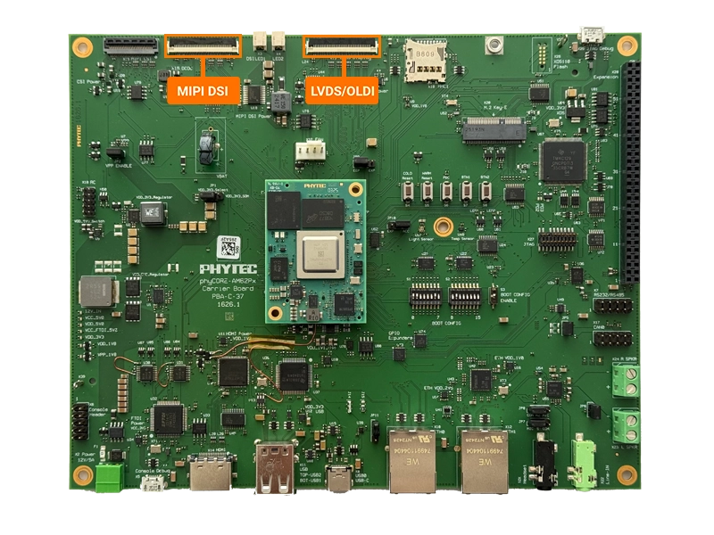
This guide will show you how to use an LCD touch display connected to the OLDI interface of the phyBOARD-Lynx AM62Px, as well as how to use a MIPI DSI display connected to the DSI interface. For more information on the display interfaces, see the Hardware Manual.
Requirements
The development kit supports the Lincolntech LCD185 10” LVDS display and the Lincolntech LCD282 7” MIPI DSI display.
Lincoln 10” LVDS Display
KLCD-185-000: A PHYTEC Accessory Kit
Included in the kit:
Lincoln Technology Solutions, 10.1” PCAP LCD (LCD185-101CTL1AGNTTR1.2)
Display adapter PCB (PCB-L0136R1.2)
1x 8” 40-pin FFC/FPC cable (opposite-side terminals, 0.5mm pitch)
5V 1A USB-C power adapter
Lincoln 7” MIPI DSI Display
LVDS Display
Connecting the Display
Power off the development kit and disconnect the power supply.
Connect the display to the development kit’s X13 connector (labeled “LVDS Display” on the silkscreen) via the 40pin FFC ribbon cable.
Open the connector by pulling the black tab backwards toward the center of the carrier board.
Insert the ribbon cable into the connector, with the blue tape facing outward.
Once the ribbon cable has been seated into the connector, pull the black tab back towards it’s closed position. You should hear a small click when the connector has completely closed.
Connect the external power supply to the LCD185 display adapter.
Loading the Display
Power on the development kit and hit any key to stop in U-Boot.
Load the device tree overlay needed for operating the display and boot into Linux.
uboot:~# setenv overlays k3-am62p5-phyboard-lynx-oldi-lcd185.dtbo
uboot:~# saveenv
uboot:~# boot
Note
For more information about overlays see chapter Configuring the Bootloader.
While the kit is booting, the PHYTEC logo with a loading bar should appear followed by a green and blue qt6demo app screen.
MIPI DSI Display
Connecting the Display
Power off the development kit and disconnect the power supply.
Connect the display to the development kit’s X15 connector (labeled “MIPI DSI” on the silkscreen) via the ribbon cable.
Open the connector by pulling the black tab backwards toward the center of the carrier board.
Insert the ribbon cable into the connector, with the blue tape facing outward.
Once the ribbon cable has been seated into the connector, pull the black tab back towards it’s closed position. You should hear a small click when the connector has completely closed.
The LCD282 display does not require external power, instead you must connect the two power connectors to the Display Power connectors on the board.
Loading the Display
Power on the development kit and hit any key to stop in U-Boot.
Load the device tree overlay needed for operating the display and boot into Linux.
uboot:~# setenv overlays k3-am62p5-phyboard-lynx-dsi-lcd282.dtbo
uboot:~# saveenv
uboot:~# boot
Note
For more information about overlays see chapter Configuring the Bootloader.
While the kit is booting, the PHYTEC logo with a loading bar should appear followed by a green and blue qt6demo app screen.
Using the Demo
Note
The qtdemo can be interacted with on the LCD by plugging a keyboard or mouse usb hub into the development kit.
The demo can be stopped by running the following command:
phyboard-lynx-am62pxx-1:~# systemctl stop qtphy