GPIO
The GPIO Example project is a demonstration program that uses the KSDK software to manipulate the general-purpose outputs.
Hardware Setup
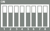
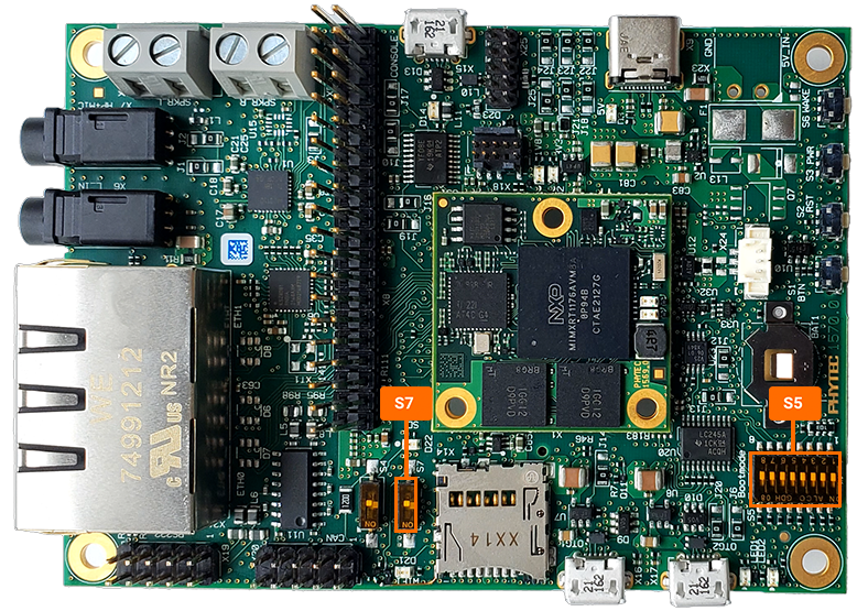
Check that the boot switch S5 is set to boot the system from QSPI flash
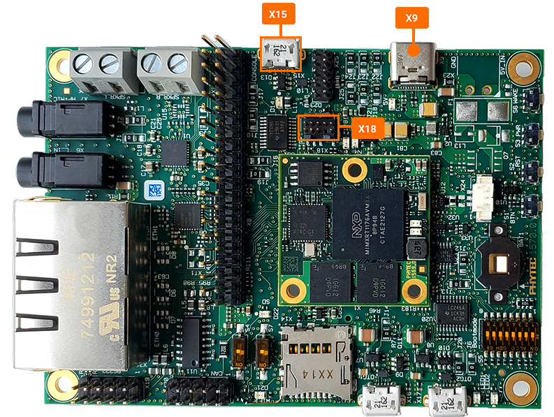
Connect the micro-USB to the USB console connector (X15) and to the Host PC, the 5V USB-C power supply to an outlet and then to the development board (X9), and the 9-pin J-link device to the development board (X18) and to the Host PC.
Software Setup
- Open a serial terminal with the following settings:
115200 baud rate
8 data bits
No parity
One stop bit
No flow control
Open NXP’s MCUXpresso IDE tool with the PHYTEC SDK installed. See the FreeRTOS Development guides to help setup both the IDE and SDK if those are not already installed.
LED Example
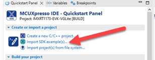
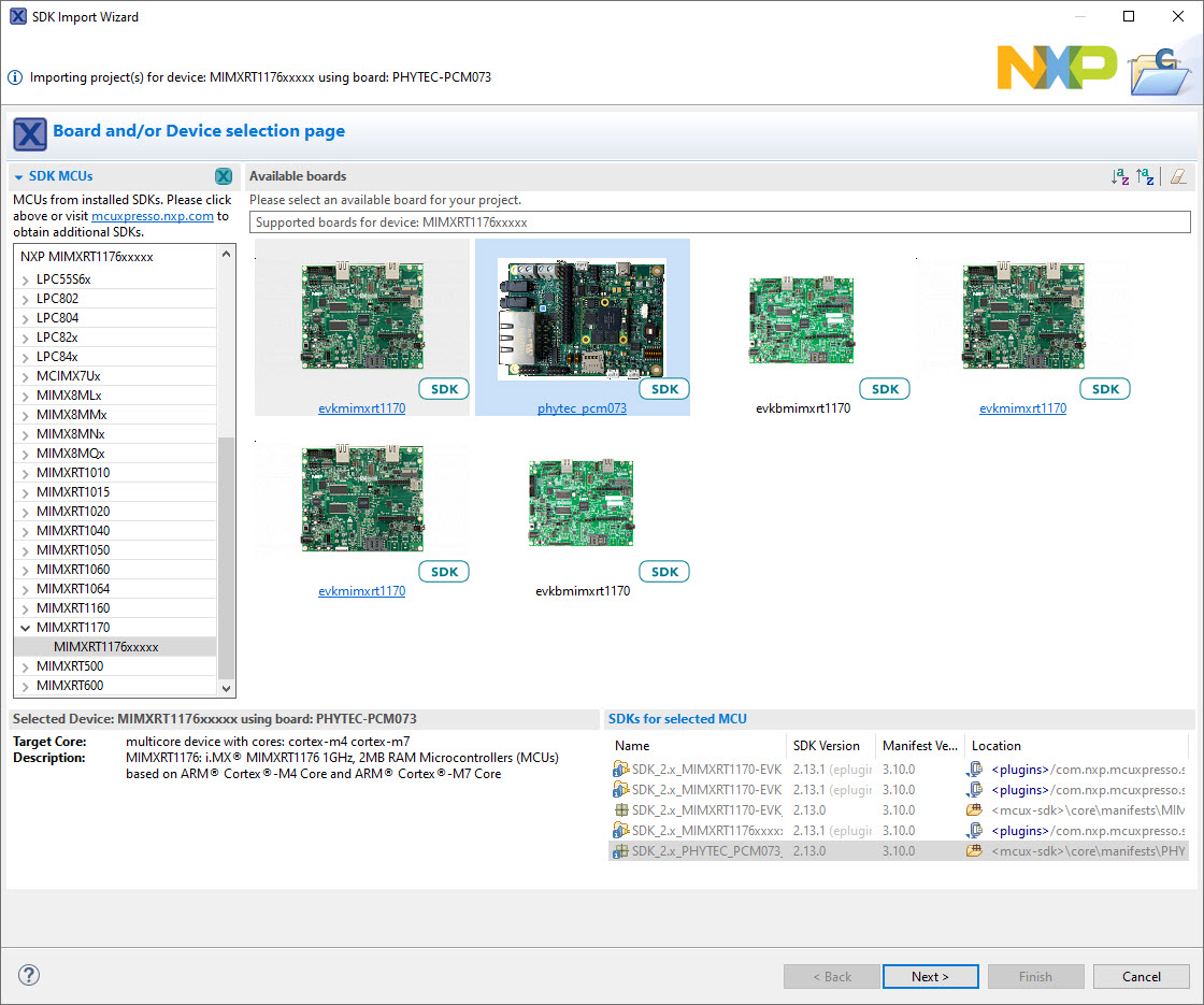
With the MCUXpresso IDE tool open, click the “Import SDK example(s)” in the left side corner.
Select the MIMXRT1176xxxxx: PHYTEC-PCM073
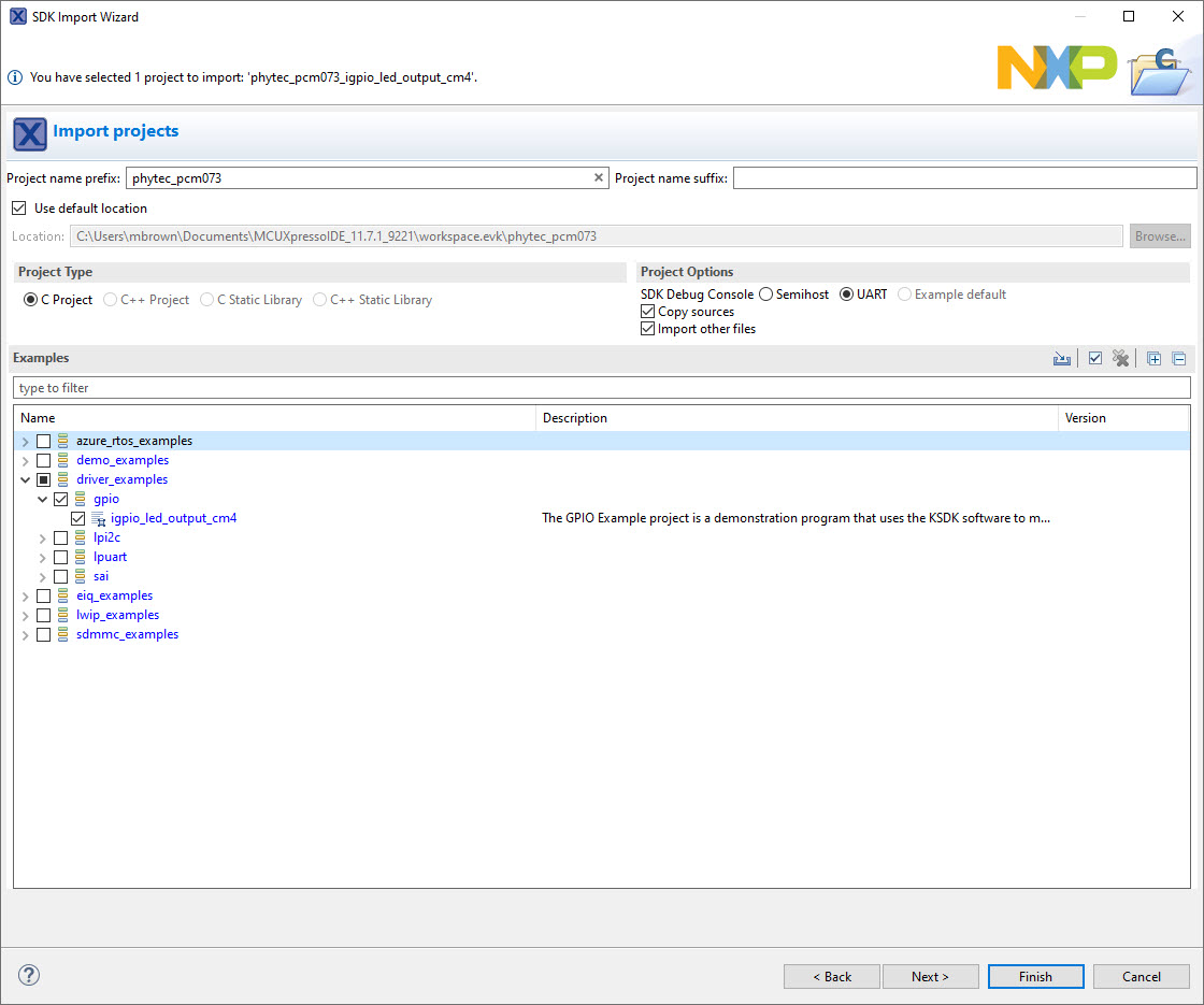
Select the driver example “igpio_led_output_cm4” and then select “Finish”.
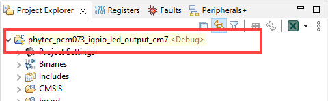
Click on the project “phytec_pcm073_ipio_led_output_cm7” then build the project.
Note
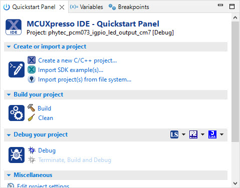
There are mutiple places in the IDE tool to find various useful functions such as build, clean, and debug. In the lower left-side corner of the IDE tool there is a “Quick Panel” window for fast access to these functions.
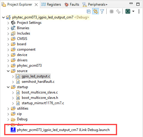
Then debug the project. A “.launch” file should appear in the project.
The project is now ready to be downloaded onto the development kit. Press the download button (at the top of the toolbar, looks like a green play button) to flash the kit.
Note
Another place to find more functions/tool in the IDE is at the top of the toolbar. This is where the download, pause and terminate tools can be located.

On the serial terminal there should be a message verify that the project was flashed.
COM PortGPIO Driver example The LED is blinking.
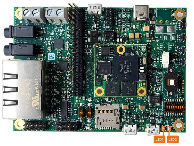
LED1 and LED2 on the carrier board should be flashing together and toggling at the rate of 100 milliseconds.
Add SOM LEDs
There are two LEDs on the phyCORE-RT1170 SOM (D7, D8). This portion of the guide will walk through how to add these two LEDs into the phytec_pcm073_ipio_led_output_cm7 SDK example.
Note
Contact the PHYTEC Support to request schematics for the phyCORE-RT1170 development kit. The component placement documents for both the SOM and the carrier board can be found on the phyCORE-RT1170 SOM product page
Using the SOM schematic and signal names and processor balls of D7 and D8 can be found. This information can also be found in the table below.
GPIO |
Processor Ball |
Interface Connector |
|---|---|---|
GPIO12_IO13 |
U6 |
LED2 |
GPIO9_IO13 |
N14 |
LED1 |
GPIO13_IO11 |
N9 |
D7: Red LED on SOM |
GPIO13_IO12 |
R11 |
D8: Green LED on SOM |
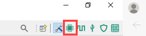
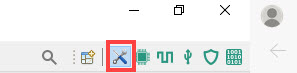
In the MCUXpresso IDE, open the pin muxing tool. The image below is located in the upper right side corner of the IDE.
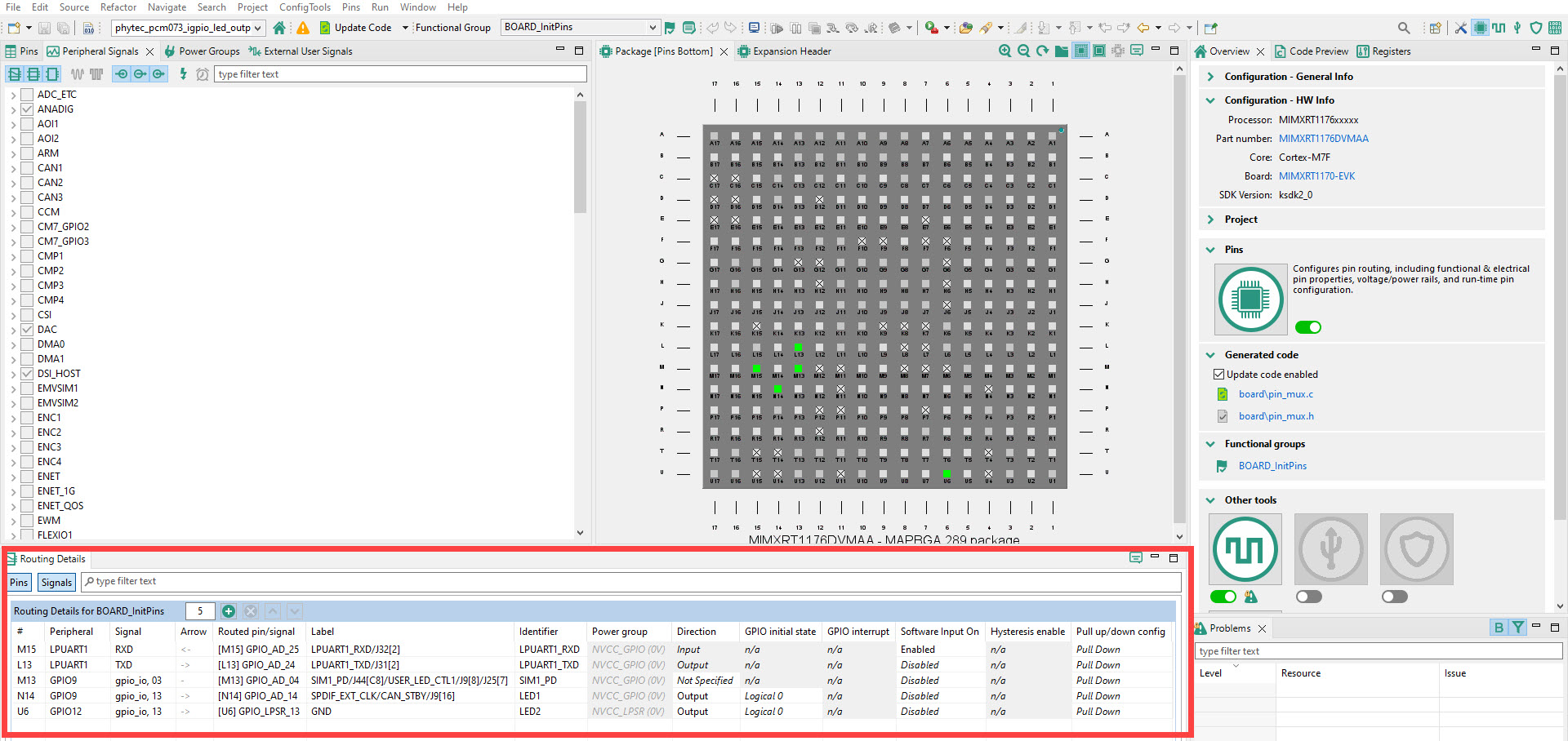
Edit thse routing details to include D7 and D8. You can either asign pins by selecting the pin on the “Pins Bottom” visual or by adding a row and typing in changes in the “Routing Details” table. There is an excel table and pdf file here for viewing ease, gpio-led-routing-details-pcm-073. In this example D7 is LEDR and D8 is LEDG.
Update the code to reflect pin muxing changes.
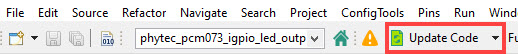
Return to the develop page.
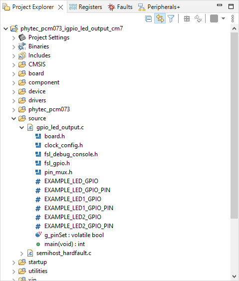
In the pin_mux.h header you can find the GPIO driver symbol names. Verify that the pin muxing changes were updated in code.
Note
The project source files can be found in the left side panel in the IDE. Also, the ctrl+f function works withing NXP’s IDE tool.
/* GPIO_SNVS_08 (coord N9), J42[11] *//*
/* Routed pin properties *//*
#define BOARD_INITPINS_LEDR_PERIPHERAL                                    GPIO13   /*!< Peripheral name *//*
#define BOARD_INITPINS_LEDR_SIGNAL                                       gpio_io   /*!< Signal name *//*
#define BOARD_INITPINS_LEDR_CHANNEL                                          11U   /*!< Signal channel *//*

/* Symbols to be used with GPIO driver *//*
#define BOARD_INITPINS_LEDR_GPIO                                          GPIO13   /*!< GPIO peripheral base pointer *//*
#define BOARD_INITPINS_LEDR_GPIO_PIN                                         11U   /*!< GPIO pin number *//*
#define BOARD_INITPINS_LEDR_GPIO_PIN_MASK                            (1U << 11U)   /*!< GPIO pin mask *//*

/* GPIO_SNVS_09 (coord R11), J42[12] *//*
/* Routed pin properties *//*
#define BOARD_INITPINS_LEDG_PERIPHERAL                                    GPIO13   /*!< Peripheral name *//*
#define BOARD_INITPINS_LEDG_SIGNAL                                       gpio_io   /*!< Signal name *//*
#define BOARD_INITPINS_LEDG_CHANNEL                                          12U   /*!< Signal channel *//*

/* Symbols to be used with GPIO driver *//*
#define BOARD_INITPINS_LEDG_GPIO                                          GPIO13   /*!< GPIO peripheral base pointer *//*
#define BOARD_INITPINS_LEDG_GPIO_PIN                                         12U   /*!< GPIO pin number *//*
#define BOARD_INITPINS_LEDG_GPIO_PIN_MASK                            (1U << 12U)   /*!< GPIO pin mask *//*
Then in the board.h file, add LEDR and LEDG.
board.h snippet#ifndef BOARD_USER_LEDR_GPIO #define BOARD_USER_LEDR_GPIO GPIO13 #endif #ifndef BOARD_USER_LEDR_GPIO_PIN #define BOARD_USER_LEDR_GPIO_PIN (11U) #endif #ifndef BOARD_USER_LEDG_GPIO #define BOARD_USER_LEDG_GPIO GPIO13 #endif #ifndef BOARD_USER_LEDG_GPIO_PIN #define BOARD_USER_LEDG_GPIO_PIN (12U) #endif
Then finally add LEDR and LEDG to the gpio_led_output.c file.
gpio_led_output.c/* * Copyright (c) 2015, Freescale Semiconductor, Inc. * Copyright 2016-2020 NXP * All rights reserved. * * SPDX-License-Identifier: BSD-3-Clause */ #include "pin_mux.h" #include "clock_config.h" #include "board.h" #include "fsl_debug_console.h" #include "fsl_gpio.h" /******************************************************************************* * Definitions ******************************************************************************/ #define EXAMPLE_LED_GPIO BOARD_USER_LED_GPIO #define EXAMPLE_LED_GPIO_PIN BOARD_USER_LED_GPIO_PIN #define EXAMPLE_LED1_GPIO BOARD_USER_LED1_GPIO #define EXAMPLE_LED1_GPIO_PIN BOARD_USER_LED1_GPIO_PIN #define EXAMPLE_LED2_GPIO BOARD_USER_LED2_GPIO #define EXAMPLE_LED2_GPIO_PIN BOARD_USER_LED2_GPIO_PIN #define EXAMPLE_LEDR_GPIO BOARD_USER_LEDR_GPIO #define EXAMPLE_LEDR_GPIO_PIN BOARD_USER_LEDR_GPIO_PIN #define EXAMPLE_LEDG_GPIO BOARD_USER_LEDG_GPIO #define EXAMPLE_LEDG_GPIO_PIN BOARD_USER_LEDG_GPIO_PIN /******************************************************************************* * Prototypes ******************************************************************************/ /******************************************************************************* * Variables ******************************************************************************/ /* The PIN status */ volatile bool g_pinSet = false; /******************************************************************************* * Code ******************************************************************************/ /*! * @brief Main function */ int main(void) { /* Define the init structure for the output LED pin*/ gpio_pin_config_t led_config = {kGPIO_DigitalOutput, 0, kGPIO_NoIntmode}; /* Board pin, clock, debug console init */ BOARD_ConfigMPU(); BOARD_InitPins(); BOARD_BootClockRUN(); BOARD_InitDebugConsole(); /* Print a note to terminal. */ PRINTF("\r\n GPIO Driver example\r\n"); PRINTF("\r\n The LED is blinking.\r\n"); /* Init output LED GPIO. */ GPIO_PinInit(EXAMPLE_LED_GPIO, EXAMPLE_LED_GPIO_PIN, &led_config); GPIO_PinInit(EXAMPLE_LED1_GPIO, EXAMPLE_LED1_GPIO_PIN, &led_config); GPIO_PinInit(EXAMPLE_LED2_GPIO, EXAMPLE_LED2_GPIO_PIN, &led_config); GPIO_PinInit(EXAMPLE_LEDR_GPIO, EXAMPLE_LEDR_GPIO_PIN, &led_config); GPIO_PinInit(EXAMPLE_LEDG_GPIO, EXAMPLE_LEDG_GPIO_PIN, &led_config); while (1) { SDK_DelayAtLeastUs(2000000, SDK_DEVICE_MAXIMUM_CPU_CLOCK_FREQUENCY); #if (defined(FSL_FEATURE_IGPIO_HAS_DR_TOGGLE) && (FSL_FEATURE_IGPIO_HAS_DR_TOGGLE == 1)) GPIO_PortToggle(EXAMPLE_LED_GPIO, 1u << EXAMPLE_LED_GPIO_PIN); GPIO_PortToggle(EXAMPLE_LED1_GPIO, 1u << EXAMPLE_LED1_GPIO_PIN); GPIO_PortToggle(EXAMPLE_LED2_GPIO, 1u << EXAMPLE_LED2_GPIO_PIN); GPIO_PortToggle(EXAMPLE_LEDR_GPIO, 1u << EXAMPLE_LEDR_GPIO_PIN); GPIO_PortToggle(EXAMPLE_LEDG_GPIO, 1u << EXAMPLE_LEDG_GPIO_PIN); #else if (g_pinSet) { GPIO_PinWrite(EXAMPLE_LED_GPIO, EXAMPLE_LED_GPIO_PIN, 1U); g_pinSet = false; } else { GPIO_PinWrite(EXAMPLE_LED_GPIO, EXAMPLE_LED_GPIO_PIN, 1U); g_pinSet = true; } #endif /* FSL_FEATURE_IGPIO_HAS_DR_TOGGLE */ } }Be sure to delete the previous .launch file and save your changes. Then build, debug and download the project onto the project.
Note
If the example does not appear to be performing, press the reset button S2.
LEDR and LEDG should be flashing in time with LED1 and LED2 now.